Floor laying continues with the Junckers System. The floor boards are 22 mm solid wood with a proprietary clip system. Each of the metal clips (shown below) connect each floor board. The clip type one selects depends on the expected humidity levels in the home. I used a soundproof underlay on the concrete floor. One can also nail this type of flooring.
Skirting Board Lighting
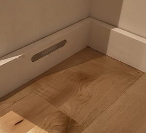
I started the design of the skirting board lighting that will be powered from a DC source (battery) connected to a solar panel. The idea is that this lighting would be on when it is dark and would also act as a lighting system if there was a power failure in order to minimise the use of candles.
The light output of this lighting would be equivalent to a candle and they are placed in bathrooms and corridors in order to allow one to walk around the house at night without switching on the main lights.
A first fix of how they will look is as shown below.
Having carried out some DIY painting in the past I decided this time I would invest in good tools as this was going to be the biggest job to date. This first entailed selecting a brand whose painting equipment is rated highly. I selected tools from the Wooster product range.
There are a few essential tools.
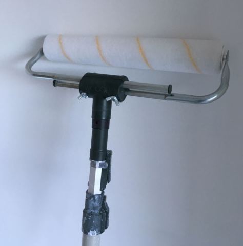
The Pole (I selected a 4 to 8 foot adjustable pole called the Wooster Sherlock GT extension pole ). This tool has a few good features such as snap on paint roller head, an extension that snaps in set positions, a tool to fit screw type paint rollers. A substantial rubber hand grip that made the job easier . The highest point of our ceilings are 3.6 metres and this version allowed me to reach the ceilings directly from the floor. Narrow hallways that are less than the length of the pole plus the roller would make it difficult to use this pole length.
Rollers– I selected a 3/8 inch nap (pile depth) for the plasterboard because of its smooth surface and I tried a 9 and 14 inch roller called the pro-doo-z. The Nap determines the amount of paint applied and the paint texture of the wall surface . The 3/8 inch gives a fine finish. If one used a 1/2 inch nap the roller can hold more paint but the texture is different. After trying the 9 inch and 14 inch roller my preference was to use the 14 inch roller as I found it easier, faster and more stable because it is supported at both ends (see below). I would be tempted to try the contract rollers that are supposed to be faster the next time but the finish may not be the same. One can select the right roller from the web site link Wooster Rollers.
Cutting In– A very useful and time saving tool was the Wooster hand-held Pelican kettle .
Pelican Kettle
It is available with liners to make it easy to change colours. It has a section to hold a cutting in brush and a mechanism to hold a small roller. Both of these are necessary in order to end up with the same wall surface texture as the main roller for example around switches and sockets. I used non diluted paint for the cutting in process. One needs a mini roller also for the Pelican holder.
Brush– The cutting in brush I used was the Silver tip wooster 2 inch model. I never owned a high quality brush before and it is working out great.
Tray/Kettle-I tried the Tray and the Kettle. My preference is the 25 litre Kettle with replaceable liners. I initially bought a Kettle with no liners and the washing out of the tray or kettle at the end of a days painting is time consuming and non environmental as one must wash the inside completely . Comparing this to using a liner that one can dispose of in the bin. I know at the end of the day it all is non environmental but using plastic liners keeps everything clean and saves time.
Safety Glasses and peaked cap -While painting the ceiling it is a vital item.
Fresh Air– While the paint is wet the smell is stronger so ensure that your rooms are very well vented. As I am painting in the winter the house temperature has dropped to approximately 9 degrees.
Paint-I used Dulux paint as it has a good reputation for quality.
Cling Film-In order to keep the brushes and rollers clean I wrapped them in clingfilm overnight. The roller lasted a week and I did not notice any problems even with this amount of time . One just took of the clingfilm and started again with no cleaning required. It also reduces waste.
Technique I used for painting
First Coat– For the first coat on the plasterboard I mixed the paint to a 3 to 1 ratio (one litre of water to 3 litres of paint) as advised. By diluting the paint for the first coat it is supposed to allow the paint to get a good bond with the paper finish on the plasterboard. I did not use the traditional wet plaster method on the walls. The paint also needs to be mixed in a separate container. One requires a 1 litre container to carry out the measuring. I experimented with a lower ratio of water and I could not see much of a difference with the Dulux matt white paint on the bare plasterboard only that with two paint coats undiluted the finish looked better . If the walls were wet plastered in the traditional way then the water mix appears to be vital.
I started out using the paint brush and mini roller for the first cutting in but later on I just used the paint brush for the first cut and then used the paint brush and mini roller for the second cut in order to finish with the same texture as the 14 inch roller.
14 Inch Roller
After watching numerous methods and comparing the comments I think the following is the best I have come across to date and having used the ideas it it all makes sense. With Youtube I found one has to watch about ten videos and then decide who is doing it right. Below may help.
When the first coat of paint is applied it often identifies small imperfections in the plastering. When this happens let the paint dry and fill the imperfection with USG or Gyproc ready made joint filler. When this has fully dried sand it by hand and repaint it with a few coats. This method worked for me.
The golden rule is-avoid sanding as much as possible by ensuring that the knife finish is smooth at the edges and as close to a final finish as possible. If one had to do this manually with a sanding block and pole it would be a tough job.
Thankfully over the years people have been improving the tools. I was lucky enough that the builder loaned me his sanding machine. I just needed a hoover to manage the dust which was picked up free on the free cycle web site. The sanding machine looks like the following:
Flex WS 702VEA
Even though the above Flex machine makes the job easier and faster it still is a physical job especially when working overhead. The hoover was not designed for the above but it worked out OK once the bag and filters were cleaned regularly.
I would suggest safety glasses when working overhead and a face mask at all times.
Technique for Sanding Used
The joints had a second coat of plaster and then a touch up coat was used to remove any edges and at the same time look for and fix any imperfections on the butt finishes (where two boards are joined with no taper edge) or tapered edges. USG 3 Sheetrock (see previous blog) was usedfor the second and third touch up coat. I would not recommend the Gyproc joint filler for the second and third coat as it is primarily used for the first coat and it does a great job. When dry the finish is very hard and it would be difficult to sand. There is a Gyproc pro finisher but I found the Sheetrock product very economical and easy to work with for the second and third coat compared to other options.
I used a 150 grit sand paper on the Flex machine and left it at speed 4. I was expecting that the sand paper would get blocked up but this did not happen. I was advised and found it very important to sand the edges of the joints and ensure that one does not stay too long on the edges as the paper on the plaster board could be damaged. A light sand in the centre of the joint is how I finished each joint.
Edge Sanding of Plasterboard
I also found it necessary to manually inspect the wall after the electric sander as one is too far away from the wall with the sander to spot imperfections. I made up a hand sanding block for this with a wood fibre board angled to get into corners.
Home Made Sanding Block
The angled wood fibre board worked out better for me than dedicated sanding blocks and I used a pre-used sanding disc from the electric sander.
Wood Fibre Board as a sanding block.
Plasterboard Corners
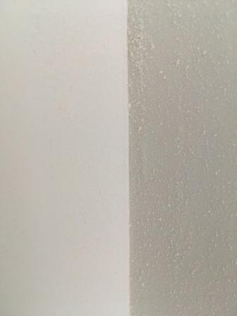
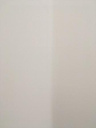
I experimented with the wall corner finishes on whether a sharp edge or rounded corners worked out better. The sharp edges looked like that shown in the top image below and the rounded corner is the image below that. If I was doing it all again I would use the rounded corners as I feel it looks better.
Plasterboard corner finish straight edge. Note dust still on one wall.
Rounded Corner
Fire Compartmentalisation
Typically with internal wooden stud walls there may be gaps between rooms at floor level or vertically. For this reason one may want to ensure that fire compartmentalisation is addressed (a previous blog covered this in detail). In order to do this I have chosen a B1 rated fire foam for the floor gaps. It also has a secondary benefit of reducing sound travel between rooms at these gaps. The foam I used was Olive PU-476. The price varies and the best value I found in Ireland was at National Seal Systems in Dublin. I also bought intumescent water based fire sealer for small gaps around the edges of the distribution board and vertical uprights where one partition meets another.
I came across information over the years that may help the self builder when it comes to retrofits (doing up an existing dwelling).
This is probably the most challenging of self builds as the options are few when it comes to insulating a house that was never designed to be insulated.
The other problem for the self builder is how well were the houses built in the first place -are the construction details good?. If they are good then it may be an easy step (it is evident that today there are problems with new builds. Could it have been any different in the past?)-for example were the cavities clean, state of repair of pointing, brickwork etc., .
A Guide to doing it right
The document below is a very good guideline on renovating an old building correctly when it has solid walls.
Check for any newer versions at their web site.
I extracted a sample of the contents from the above guide by way of example.
It also needs to be realised that by adding insulation to a wall that was not designed for insulation can make the house colder if the solution is not correct, structurally damage the wall over time or cause mould on the inside that may affect your health. The above report goes through this.
Objective
The above will hopefully guide the self builder away from the problems and find the correct solution.
One needs to fully understand that one needs to choose the most robust solution that can withstand something going wrong.
Possible Products
Some of these products may be safer to use when it comes to old buildings . Some require extra measures to ensure they keep the building dry and you warm.
Having recently come across a best practice guide for Electrical installations and their effect on the fire performance of buildings I have decided to change the approach to the fire/acoustic isolation between rooms. I will now install Rockwool flexi 50mm in the 100mm partition walls and Rockwool flexi 100mm in the 140mm partition walls .
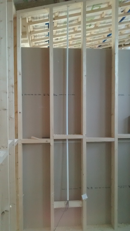
Partition before Insulation with Wiring
Partition wall with Rockwool installed
From an acoustic perspective I was advised that it is better to install the Rockwool in the centre of the partitions rather than touching one or other side of the plasterboard as this limits the sound transfer.
The Electrical Safety Councilbest practice guide deals with Electrical installations and their impact on the fire performance of Domestic premises at thislink when one is building a home. A summary is as follows but the full document is worth reading for any self builder.
Fire containment in the event of a fire
The need to prevent fire from passing through holes in all elements whether solid or lightweight is addressed.
Electrical Equipment is identified that has a direct and significant influence on the fire performance of an element.
Partial Penetrations –those that reduce the fire performance of part of the wall/ceiling or floor.
Full Penetrations-such as ducts and fans that go through both elements of a wall/ceiling/floor.
I plan to install as much of the plaster board by myself. There are different techniques for completing the finish. I note that one must use paper between the joints in order to maintain the fire proof rating and the paper jointing material provides superior resistance to cracking. (see www. Gyproc.ie Jointing document)
It appears that the plastic mesh is not to be used even though it is popular.
When the boards are in place there is a special plaster joint coating for the first two coats and a different jointing plaster is used for finishing the joint.
It appears that we will not be able to plaster finish the complete boards as the humidity level in too low and there is a risk that a coat of plaster may crack during the drying process.
For the bathrooms areas around the shower I plan to use magnesium board or cement board as it offers superior water proofing.
Applying the plaster to the joints.
Below are a few videos I located in order to watch and learn from the professionals.
More details that may help
Tools
An important tool if one is doing the plaster board oneself is a plaster board lifter .
Some of these have height restrictions . Some are very professional and expensive and some are low cost. They vary between €150 and €1000.
Some plaster board web sites that I located to date are
I recently came across a few videos from America on the subject of building physics. They may help the self builder when trying to figure the wall system, roof design or insulation to use.
The videos are presented by Joseph Lstiburek who outlines the do’s and dont’s in a very direct manner. He is the founder of Building Science Corporation.
In the videos he references the American method of describing heat loss which is the R value (resistance to heat loss per inch- a higher number is better) while in Europe we mainly use the U value (ease in which heat travels through an object-a lower number is better but it includes boundary air films). The Rvalue is the thickness of the insulation divided by the K value or in the examples presented by Joseph Lstiburek the R value of 2 of the Irish building is approximately equivalent to a U value of 0.5.
This video starts with the progress for insulating buildings in 1000 years (starting with an Irish Church) and covers the perfect wall, roof and slab and the importance of designing buildings for the climate they are situated in.
Video (Below)
Commercial Thermal Bridging , LEED Building Problems, Water problems.
Physics Discussed (2nd law of thermodynamics)
Heat flow is from warm to cold
Moisture flow is from warm to cold
Moisture flow is from more to less
Air flow is from a higher pressure to a lower pressure
Gravity acts down
Quality Assurance-Figuring out what the right thing to do is
Quality Control– Executing it
The building layer order of importance for a wall, roof and slab and the importance of continuity between the layers as shown below in order of importance.
Water control layer
Air control layer
Vapour control
Thermal control
The 500 year wall-Keep the water out of it. Allow the vapour to get out from the inside or outside if it gets in. Keep the air out of the wall from the outside and inside. Put all the thermal layers on the outside and put the cladding on the outside.
He also analyses the LEED energy standard.
To Vent or not to Vent (Roofs-cold, warm and SIPS)
This video covers venting and airtightness of SIP roofs.
What happens when one uses a white roof membrane versus a black one.
Building Enclosures
Why increasing insulation is a game changer in the future . Moisture and durability issues that lie ahead because of extra insulation.
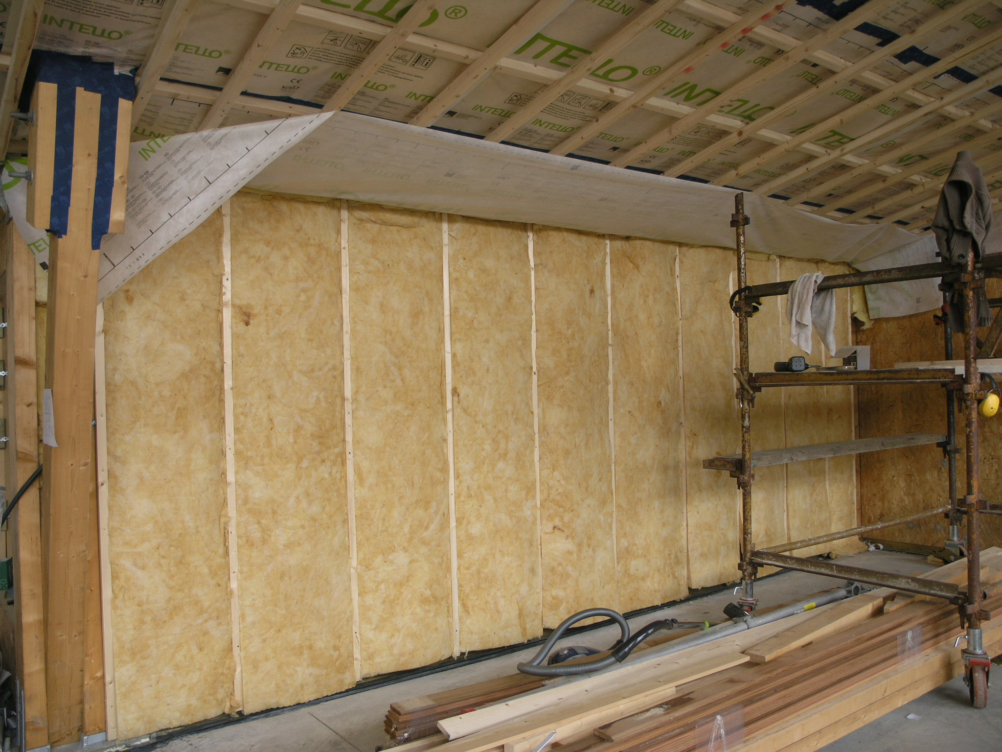
For the internal wall build up I am using a double batten wall system. This wall system allows one to easily install services. In a previous experiment on building a workshop (used as a means to experiment on a small building before commencing the house) I installed a single row of horizontal battens on the OSB board. This made it very difficult to run services that need to run vertically. I had to install metal protecting plates and cut notches in the wood in order to ensure that I did not damage wiring due to the final layer of plasterboard screw fixing.
When one uses a counter batten system it facilitates running services such as power, lighting, phone, internet, alarm etc without the risk of screw damage. This system also helps to reduce the cost of installing these services (see the image of a cable behind the batten below).
One can make use of a wall system like this if a soft insulation such as cellulose or fiberglass is behind the final batten which will support the plasterboard finish.
A row of battens run vertically behind the membrane in order to facilitate running services.
When working at ceiling level one may need to use a counter batten system in order to allow for recessed lighting otherwise it will mean installing special electrical enclosures cut into the airtight membrane. I have installed counter battens to a depth of approximately 90mm in the living and kitchen areas for LED downlights (see the previous post link on the 26/04/2015). In the bedroom areas I will only use a single batten system in order to install hanging pendent fittings.
Floor Level Insulation.
At floor level I installed Rockwool insulation for two reasons -one was to minimise the thermal bridging (heat loss around the wooden sole plate that the timber wall sits on) and the second reason was to minimise the damage to the insulation if there was a water leak.
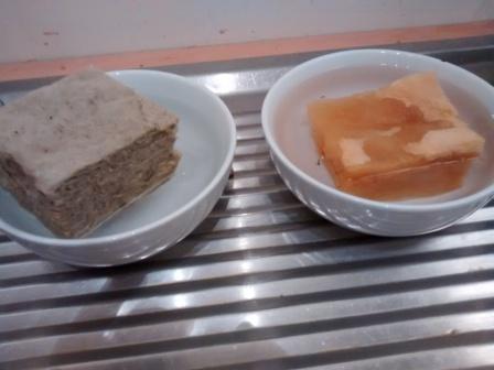
I carried out a test where I placed 50mm of Rockwool RWA45 (product in the left bowl) and Metac (fiberglass-product in the right bowl below) in water in order to see what would happen if there was a leak. The Rockwool absorbs very little water but the fiberglass sank and became completely saturated and would possibly never dry out. Both insulation’s were submerged initially and then left for the duration of the test.
Rockwool versus Fibreglass for water damage.
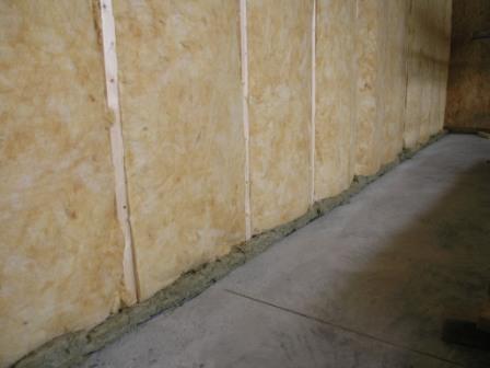
Below is an image of the Rockwool installed at floor level under the fibreglass in order to minimise the risk of insulation damage at floor level and minimise thermal bridging.
Rockwool Installed at Floor Level (green colour)
Airtight Membrane Installation
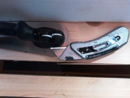
When installing the airtight membrane I was surprised how quickly the knife goes blunt. Rather than using the disposable knives and blades I now use a sharpener with the knife.
There were a number of choices when it came to the exterior cladding. Because the house is a timber frame I went for a ventilated facade with cement boards. The decision for selecting this was based on the following:
Because the house is highly insulated very little heat will travel through the wall structure. This entailed changing the wall build-up on the advice of our timber structural engineer. On a normal timber frame one installs a rigid OSB board on the outside and this then would typically be covered with a membrane and then battened for the cement board or tied to block work. When the timber structural engineer carried out a Wufi analysis (hygrothermal analysis-how the wall behaves with our humidity levels in Ireland) he advised that the structural strength of the OSB board would be affected if we placed it outside because of moisture build up. The OSB was then placed inside with only the vapor barrier on the outside and then the outside was battened /counter battened for the cement board.
My preference was to use block work on the outside (because of cost advantage) but this showed up in Wufi as needing large amount of ventilation and it would not perform as well as a cement board or a wood finish wall. It seems that if one used block work the heat from the sun would take a long time to reach the ventilated space. The ventilated space it appears requires two pieces of physics to work correctly-Thermal Buoyancy (warm air rising and creating a drying out environment) and Wind for the ventilated cavity. Relying on one of these I felt was a risk I did not want to take.
The other reason for selecting a ventilated cavity versus using an externally insulated (with a non breathable product) was the provision of a second level of protection to the wall structure if there was a fault in the external waterproofing . If for example water leaked in around a window detail it would dry out if the wall was ventilated but if water got in behind a wall that was externally insulated with Polystrene/EPS/PIR/PU the opportunity to dry out was I felt limited.
By selecting a cement board (around 12mm thickness) if the sun shines on this it would within a very short period of time let the heat transfer to the inside of the ventilated cavity and increase the drying out of the wall and also keep the insulation dry so that it can perform at its rated value.
Some Details
The membrane was glued around the external structure of the timber frame and wall to ensure that no wind would be blowing over the face of the insulation ie. Minimise thermal looping.
Membrane glued with Orcon F to concrete and wood structure
The membrane was placed over the Insulation and glued to structure as seen above.
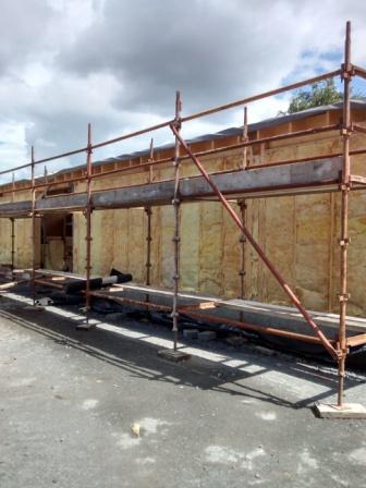
220mm Metac Insulation placed between external structure before membrane applied.
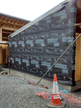
External Membrane applied over Insulation
Membrane covering Insulation
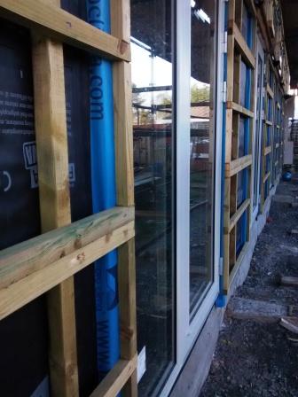
Battens for Cement Board Cladding
Counter Battens On Window Walls
Aluminium ventilation vents for walls.
Aluminium Ventilation Grille
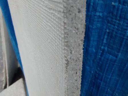
Cement Board sample
Cement Board Sample
The Cement Board is screwed onto the battens with stainless steel screws. A base coat and mesh is applied first and then a primer. The final finish is a Ral colour acrylic render to make the cladding water proof. If one has a walls facing south west and they are subjected to high rainfall it may be better to install a Silicone Silicate render or check that a chemical agent is included to reduce/eliminate algae growth that can appear as a green discoloration on the render over time.
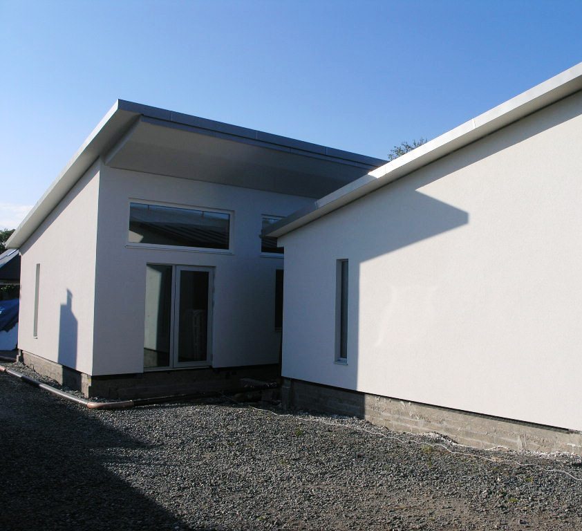
Acrylic Render Finish
The overhang underside was also clad with an acrylic render. The image below shows the overhangs shading the top windows. For example by around 9:30 AM in June the top windows are completely shaded for the sun and by 14:30 all the lower windows are in shade in order to protect the building from overheating.
Inter-connector between two buildings with 1.8m Overhangs.
I have started preparing the internal walls for more insulation, air-tightness and the service cavity .
First Wall with 50MM Metac insulation between vertical battens
There appear to be no hard and fast rules on mounting the battens and counter battens . Below are the Gyproc guidlines:
“Horizontal application of plasterboard on walls is generally recommended because it: • Reduces joints by up to 25%. • Provides a stronger wall. • Reduces the possibility of unacceptable light reflections around joints. • Joints are at a more convenient height for finishing.
However, the orientation should be chosen so that – any critical light falls along the recessed joints; the number of butt joints is minimised; a single sheet may be fixed vertically where it covers the whole wall. Nogging is not required behind recessed edge joints in horizontal applications. Partitioning fixed to steel framing in commercial applications is typically sheeted vertically. The lower edge of wall sheets is to be kept a minimum 6mm above the finished floor level. Ceiling sheets are to be installed with the long edge at right angles to the direction of the joists/main support members.”
The important factor is batten spacing . A good spacing it apears is 400mm for the plaster board. I am installing the first row of battens vertically at 600 centres. These will carry the next row of battens for the plaster board at 400 centres. I am placing the final row of battens horizontally in order to facilitate wiring and services. Fixing the plasterboard with screws appears to be better than using nails (Nº6 Type ‘W’ for timber framing a different screw type is required for other systems.)
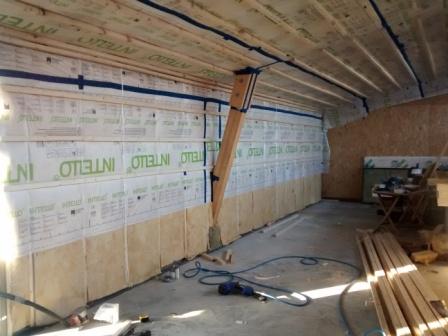
Wall Membrane and Airtight Layer with Battens
I used screws and serrated nails on the vertical battens. This layer of vertical battens will hold the 50mm metac insulation (see above and below). Next will be the airtight membrane followed by the horizontal battens. I will be placing 15 mm plaster board on the inside walls and ceiling and I am considering some other suitable board like a magnesium board (Mgo).
All the north facing walls will have cupboards/wardrobes placed in front of them. It allows me to practise knowing that they will not be seen again. I am also considering mounting the plaster board vertically on these walls as it will take one sheet exactly (2.4metre high).
Rockwool at Floor Level to minimise thermal bridging
Service Cavity
A small length of the lower floor section in the kitchen will have a service route specifically for pipes and wiring behind the skirting board. (I want some way of accessing these in the future without taking the wall apart .)
Insulation at floor level
At the floor level where the sole plate sits on the structural ring beam I am placing rockwool in order to reduce the heat loss (thermal bridge). It appears that rockwool has superior fire resistance-I must do a test this week and see for myself.
Wall Layers with Insulation
Above is a sketch of the wall build showing the basic components. For passive house certification I need to calculate the thermal bridge losses (linear heat loss) at this floor/wall junction. If I did not apply the rockwool insulation I would have significant heat losses and possibly condensation issues. I will calculate the thermal bridge losses using the free Therm software. It will show the real performance heat losses and condensation risks if any.


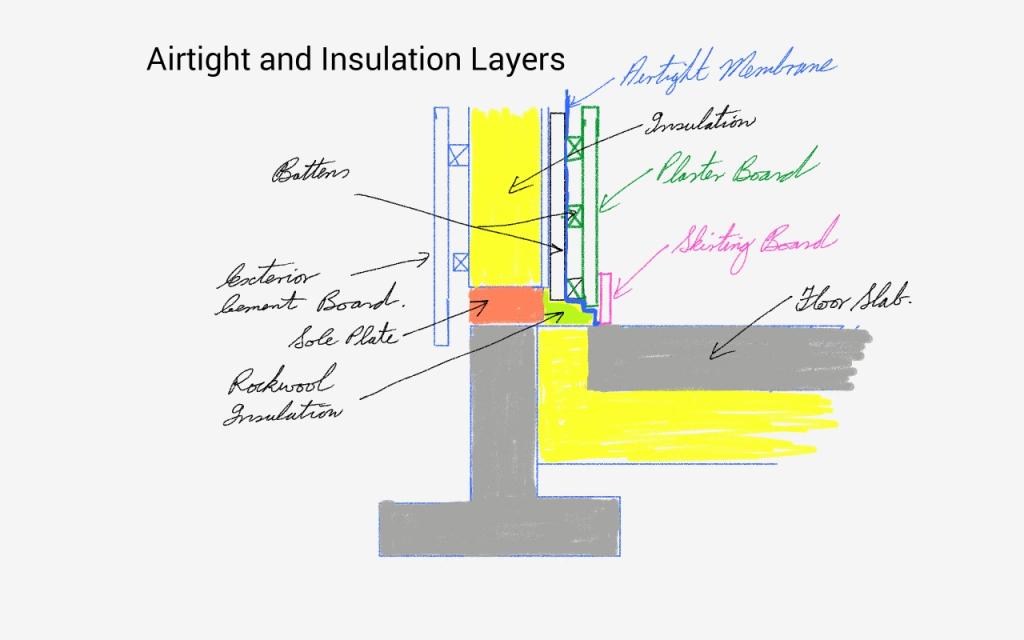 Wall Layers with Insulation