There are two types of HRV units that I came across -Heat (HRV) or Energy (ERV). The ERV is used principally for recovering humidity and heat. I selected a HRV unit,
Size Matters
When selecting a HRV unit it appears that one of the biggest mistakes is to select a unit that is too small but still satisfies the current regulations. What appears to happen in the competitive world of quotations is that a unit that just ticks the box comes in as the best price.
In selecting a unit for our home I selected a unit that has a manufacturers capacity of 542m3/h where the floor area of our house is 205 m2. Currently the unit is running at 31% of its capacity and it is maintaining a CO2 (Carbon Dioxide) level of around 700 ppm when the four of us occupy it . I use a stand alone CO2 sensor to measure the CO2 in different rooms. (I have not commissioned the unit yet as the internal doors/glazing are not installed).
Another advantage of selecting a larger unit is that it can run more efficiently at lower speeds and generates less noise through the ducts or from the unit itself.
Some of the options from the manufacturer Airflow (my unit is the third from the right).
A choice from one particular manufacturer.
September 2018 performance (with no heating switched on yet).
The graph below gives an idea of how the HRV works when managing heat from the house and supplying fresh air. For the coldest days of the year so far (2 degrees at night-in September) I put the unit into summer bypass mode the next morning (take in outside air directly and pump it around the house) because the sun was shining that day. The winter sun is lower in the sky so solar gain increases in the winter (when the sun shines). The house is made of timber/glulam construction. The main thermal mass is the concrete floor at the moment soon to be covered by a 32 mm thick wooden floor so the response times of house I suspect will change. The floor and wall temperatures are approximately 22 degrees Celsius.
Example above of HRV in use in our home.
Sample Data in our home using Google Fusion to visualise the HRV data for a week in October. (see link below)
One can select the chart tab and visualise the graph.
Use the bottom graph to zoom in.
The data is from the 21 October to the 28 October 2018.
One storage heater rated at 1.7kwh was used for 5.5 hours a day off peak.
The storage heater was switched off for one day on the 23rd October.
The graph starts at midnight on the 21 October.
Each ref reading is every 10 minutes.
The CO2 reading vary between 480ppm and 700ppm when fully occupied.
All HRV units contain a maintainable part called filters. They have a number of functions.
Clean the air being pumped into the house, and
Keep the internal components such as fans, ducts and HRV housing clean.
One typically finds one coarse filter and one fine filter on the air supply into the house and a coarse filter on the extract air from the house before the extract fan. The coarse filter is typically a G4 and the fine filter is a F7 (Pollen filter). I installed a 400mm x 400mm G4 coarse filter at the duct inlet so that I could keep the main supply duct clean. It is a bit more effort to maintain this but it will hopefully minimise the maintenance of the duct.
Self Build air tightness test -0.22ach with a volume of 603 m3 @ 50 pascals.
When one is building to a performance standard the day of reckoning is the airtight test. The reason for this is that when one is pumping fresh air into the house using a Heat Recovery System, rather than relying on simple multiple holes in the wall, it becomes important to control where the fresh air is coming from and where the heat is going.
Airtight Test
If air is leaking in or out around windows /doors/walls or other gaps in the building fabric then heat is lost and moisture problems in the form of mould can arise or else give rise to damage to the building fabric.
The pressure 50 pascals equates to a 20 mile per hour wind which is not too untypical in Ireland. So if one opts for the Irish building standard (a minimum standard) this equates to the air in the house changing/leaking 7 times a hour when a wind blows at 20 miles per hour. No wonder people block up the hole in the wall vents .
The current Irish building standard require 7 air changes per hour (ach) also called leakage at 50 pascals typically with no heat recovery system. As a guidance heat recovery manufactures recommend 3 Air leakages per hour to ensure that the heat recovery system can push fresh air into the house and recover heat leaving the house through its own system rather than through gaps in the building fabric.
The passive house standard for a new house requires 0.6 Air changes per hour (ach) at 50 pascals to ensure the heat recovery system works efficiently, ensure that occupants receive the correct amount of fresh air and minimise building fabric damage.
The passive house test differs from the Irish test because it must include pressurisation and depressurisation and use the volume as set out per Vn50 (EN13829).
The Test
Gavin O Shea from Greenbuild was hired for the job. He is certified/audited by the National Standards Authority of Ireland (NSAI).
The preparation for this entailed sealing all cable ducts and the inlet and outlet pipes for the Heat Recovery System. One also ensures that the shower and sink outlet traps are full of water. The overflow outlet for two water tanks were not sealed off. I did consider a duck valve but it was not in place at the time of the test.
Airtight Test
The test using the Irish method gave a result of 0.181 m3
/(hr.m2).
Gavin O Shea calculated that the equivalent size hole that equates to a result of 0.22 ach is approximately 65.25 cm2 (@50Pa) or a hole 81mm x 81mm if all of the leaks present in the dwelling were concentrated into one hole. That is about a tenth of an A4 sheet of paper.
The results of the air tight test can also help determine the selection of the Heat Recovery System. If the airtight test is lower then more options are available when selecting a unit.
From my research a passive house standard Heat Recovery Unit will cost more because it needs to be independently tested by the Passive House Institute using their test method. Heat Recovery manufactures have also the burden of putting the unit through national tests or international tests with the end result being the customer pays more. One has also the option to select a non passive house certified unit for a passive house but when calculating the performance value one needs to account for this in the PHPP software with a 12% reduction below the manufacturers performance claim.
If one wants to view certified Heat Recovery Units one can find and sort them at the following link. One can see for example at this link the capacity (Column- Air Flow Range) that these units have as it is important to select a unit that is oversized for your particular self build. I would compare it to selecting a mini car to tow a caravan up a hill compared to using a larger car. The small car will struggle from an efficiency and noise point of view while the larger car will be quieter and more efficient at the require flow rates. I will do a separate post on how I selected our Heat Recovery Unit.
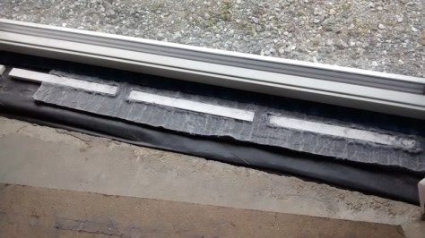
Below is the plan to deal with the window/door threshold detail to minimise thermal bridging and provide airtightness.
The window sits on a 30mm piece of Compacfoam . I used Compacfoam 200. I rebated the Compacfoam under the window so that the floor boards would fit under the window and sit on the non rebated edge.
Compacfoam 30mm with rebate (Used router to rebate)
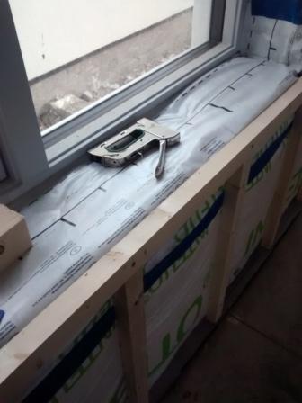
I placed 15mm Compacfoam along the lenght of the window and glued these with Orcon F. The direction of the Compacfoam will determine the floor board direction.
Strips of Compacfoam
I then used 15mm Aerogel to seal around the Compacfoam. Under the window I installed the Proclima profil tape so that I could tape the Intello membrane later.
I left the centre protection tape in place on the Intello profil so that the wooden floor would go in as far as possible on the membrane.
Aerogel 15mm
The Intello membrane was then taped ensuring that it was placed as near to the window as possible . I taped the membrane to the floor . This finished the detail.
Proclima Solitex Plus in place
An example of the possible future wooden floor sample in place is seen below or stone/slate or marble finish.
I will first seal the floor with a product from Lakeland paint in the UK in order to minimise dust. (It looks like a very high eco specification sealer ).
I then plan to install a marble /stone slab to bridge the gap and connect this to the wooden floor.
It is now time to research the solutions available in order to guarantee a fresh air supply into the house, extraction of the stale air and recover heat before the stale air is sent on its way.
There are a number of options -Use the hole in the wall in each room (with no heat recovery), use a central extract system (with no heat recovery), use decentralised heat recovery or a fully ducted heat recovery system .
From previous experience and research the hole in the wall system does not work well taking into account that we have a wind speed of almost twice that of Germany. The system creates draughts and one has only to view the number of vents blocked up and the dependence on the correct speed of wind blowing to supply fresh air in Irish dwellings to realise it does not work.
The central extraction systems either using the stack effect (using temperature differences between the inside and outside) and Bernoulli’s principle (using wind) with no fans is an option. One can use extraction systems that are powered by fans. These do work it appears but they need careful design .
Localised vents in different rooms that use heat recovery such as the Lunos , Aereco and Glidevale iMEV system offer powered heat recovery but when I priced these they were more or less the same price as a fully ducted system and require more holes than I want through the fabric of the building.
Another system recently certified by the Passive House Institute is a heat recovery system that requires two units at either end of a building called (fresh-r). I can see the system working in an open plan environment but the cost is more or less the same as the other solutions above.
If one wants to compare certified heat recovery systems one can use the certified component list on the passive house web site Certified Heat Recovery Products. These products are independently tested by the Passive House Institute.
I will be selecting a centralised heat recovery system because I feel if it is specified, designed , installed and commissioned correctly it offers the best solution. I also plan to use it as a clothes dryer in order to get extra value out of it.
What is in a typical centralised Heat Recovery System,
It typically has two energy efficient fans, a plastic heat exchanger, filters to clean the air, enclosed in an airtight box and a means to control the fan speed. It is a simple unit but the cost is high (in line with the price of other systems above except for the hole in the wall or a stack system)
I was informed recently that the Passive House Institute charges heat recovery manufactures around €60,000 for testing and certification and then there are ongoing yearly costs that need to be passed down to the consumer. A Heat Recovery Company also needs to pay for National test (separate to the Passive House Institute) in different countries which also needs to be passed down to the consumer. There appears to be no European standard test that can satisfy all EU countries.
The product I was originally interested in was from a company called Paul but for some reason the price has risen substantially- I received a price for a Paul 450 unit two years ago and it was €2000 . It is now nearly €3000 -why?. One reason is that that the product was taken over by another HRV supplier Zehnder. I will try not select these products as I see no reason why the price of the unit increased by nearly a €1000. The price above is for large air supply volumes. A three bedroom house may only need a small unit costing 50% less.
Alternative Choices
One of the highest energy efficient certified units available is from a company called Maico-an Irish representative is available. Prices start at around €2400 for a more efficient unit than the PAUL unit . Other options are from Brink such as the Excellent 400 plus also available in Ireland. Systemair Gmbh also have units available in Ireland.
Ducts
I did not think this area was going to be as complex as it is. Lets start-there are different choices of ducts from metal round, plastic round, flexible round, rectangular and all other types of shapes. The bottom line is that large round metal ducts (150-200mm) are the most efficient and quietest and have the lowest air speed.
The flexible ducts vary between two types either Aluminum or Polyethlene with general sizes between 125mm (steel), 90mm, 75mm and 65mm. The smaller the duct equates to more losses- an increase in noise and possible draughts because of the higher air speed (careful placement and selection of the outlets in rooms to minimise these effects are important). I will be trying to select and use a 90mm semi-rigid duct (outside diameter) or larger steel duct. I want to avoid the use of the 75mm duct and all its permutations such as each room being supplied with two 75mm ducts in parallel.
Larger ducts need mufflers or silencers as room noise can travel between rooms . If one has an attic or one can find a way to install the 125mm steel duct with insulation in particular routes the larger ducts may be the best way to go.
Be aware that installing a false ceiling can double the cost of the HRV. I will review all possible systems of ducts . If one uses steel I have been advised that one needs to insulate these as it can take a long time to heat up if the temperature drops leading to colder air being supplied for the initial start up.
The flexible ducts have multiple accessories to connect each part and extra cost is associated with this. The weaknesses of extra connections affects reliability. I will try and simplify the system of connections (somehow).
Ducts need to be cleaned (design and plan for this)
Keep the duct lengths short and straight to minimise losses.
Use large radius bends rather than 90 degree bends.
Consider placing ducts in the foundation when building new.
Some plastic ducts are antistatic (minimises dust collection on inside)
Some plastic ducts have antibacterial liners
Some plastic ducts are odourless and use physiologically and toxicologically safe polyethylene.
Some plastic ducts are smoother on the inside than others (minimises losses and reduces noise).
The non monetary factors for using a centralised Heat Recovery System that I can think of are:
■ comfort (help to filter diesel particles , pollen, outside smog etc from the forced incoming air)
■ building protection and health/hygiene (remove high level of moisture from cooking, showers, baths, and people that could damage the fabric of the building, CO2 from persons in the house and VOC (chemicals from furniture, beds, floor carpets, paints, plastics etc) and supply enough oxygen to get a good nights sleep. Reduced noise because windows do not need to be left open and no holes exist in the outer walls of bedrooms.
■ security (can keep windows closed)
■ thermal energy efficiency (recover up to 90% of the heat energy leaving the building)
The Plan
I want to see if I can design the HRV with the 150/125mm steel ducts or use the 90mm polyethylene outside diameter ducts with the antibacterial liner, antistatic liner and low emission polyethylene.
Each of the polyethylene ducts return to either a supply manifold or extract manifold (see example below).
HRV Manifold
If I end up selecting the 150/125mm steel ducts these will use no manifold and the individual rooms are tapped into the main duct.
Extra Functionality Planned For the HRV
In order to get the most value from the centralised Heat Recovery Unit I plan to make a special cabinet to dry clothes using a feed and return air supply. I will add a heater to the cabinet to give the clothes a drying boost where necessary.
Calculators
An interesting calculator I found is one that calculates the losses of ductwork and air speed. One can experiment using rectangular versus round ductwork and the inner roughness of the ductwork here. One can see the air speed change as one reduces the size of the ducts. There are another few options on the right hand side menu to calculate other factors.
Example of Duct Losses
Flexi Duct
Background Research and Notes
MVHR are not a fit-and-forget systems
Based on European CEN Standard 13779 ventilation for ‘medium’ air quality should be at least 10 L/s per occupant (15 L/s for high indoor air quality).-non residential
Ventilation rate of 8 l/s (30m3/h approximately) per person identified in CIBSE Guide A8
In order to achieve an air exchange of about 0.33 ach (air change per hour), one would have to open the windows wide for 5 to 10 minutes every three hours – even at night! –Source
Biggest complaints -noise and draughts (over dining area, bedroom areas etc) causing users to switch the HRV off.
Balance the air going in against going out-not practical to reach 0%. Aim for less than 10%-allowable imbalance between intake and exhaust air flow for these systems is 10%
Filters not changed can increase (double) the cost to run because the fans use more electric power to send air around.
Ensure that the HRV is accessible in order to change the filters.
A good strategy for the summer appears to be to reduce HRV speed/flow rate and open windows.
Total cost of HRV if left on appears to be around €60 for electricity and €60 for filters (Once a year). Check cost of replacement filters for own unit.
Ducts need to be cleaned every few years so the design needs to make it accessible.
A larger HRV unit than required can be more silent because it does not have to work near its full ventilation capacity.
A measured air noise level of less than< 24db for bedrooms (Finnish Guideline) . Can it be specified and delivered?
Noise levels up to 30 dB(A) were described as “too noisy” by more than 40 % of respondents. The standard for certified PassivHaus dwellings [13] is a limit of 25 dB(A) in both living rooms and bedrooms. Source
Maintaining indoor humidity below 7g/kg should help to reduce the risk of excess mite growth.
Note that air speeds greater than about 0.3 m·s–1 are probably unacceptable except in naturally ventilated buildings in summer when higher air speeds may be desirable for their cooling effect.CIBSE Guide A8
Significant problems were found with the commissioning of HRV systems, with only 16% of systems being found to have been commissioned correctly with respect to air flow and balancing. Source
44% of kitchens meeting the minimum requirement of 13 litres per second.Source
Measured air flow in 88% of systems utilising rigid ducting were equal to or greater than their design air flow values, whereas between only 40 and 44% of systems utilising flexible ducting met their respective design value. Source
Any leakage through the dwelling envelope will have an impact on the efficiency of the heat recovery component. Source
Lack of appropriate airtightness, lack of complete commissioning, poor air flow and extract rates (and associated lack of compliance with regulatory standards), lack of balance and inappropriate duct types. Source
Wolfgang Feist@WolfgangFeist-You don’t believe this?The “trick” is:We have a F8 fine filter at the external air (“fresh air”) inlet, therefore supply air is very clean
In another technical paper the following was noted as the cause of excessive noise. The source of the document is here
Extract from document shown below
“The following list of issues are all taken from actual findings on investigations that have been reported. Issues that can lead to excessive noise for occupants are noted under the following headings of design, installation, commissioning and maintenance.
Design issues
• Centralised MEV or MVHR unit located in inappropriate place for break out or structure borne noise, e.g. bedroom cupboard or on rafters in loft above a bedroom.
• Poor ductwork layout – too many bends can lead to additional fan pressure requirement and regenerated noise
• Specification of flexible ductwork
• Inadequate attenuation of duct borne noise
• Installation issues
• Ductwork kinked or damaged inhibiting flow
• Ducts not connected up to supply or extract valves (which will inhibit flow and require higher fan setting)
• Wrong type of outlet fitted (using extract outlets for supply air can lead to regenerated noise)
• No anti-vibration mounts used
• Failure to ensure ductwork is clean when installed prior to commissioning
• Use of flexible ductwork where not specified”
Recent Research
I note the above is summarised at the recent passive house conference (see below).
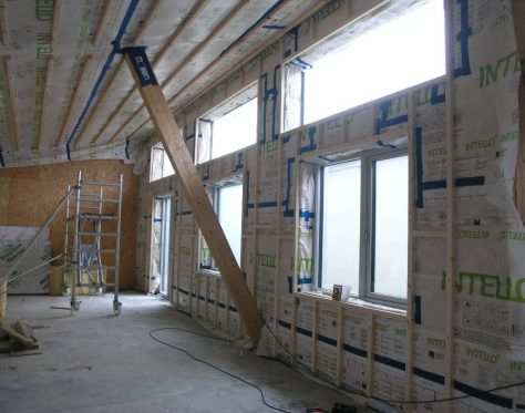
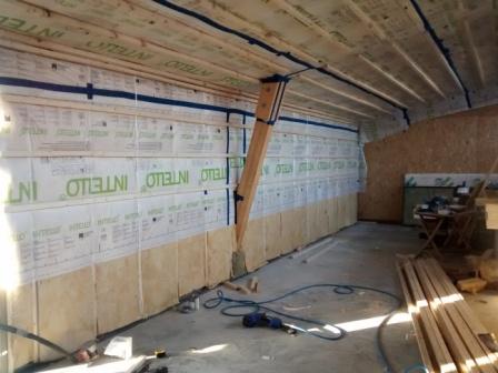
Below are a few images of the build-up I used around the windows. The first image shows the batten (45x40mm planed ) build up on the window wall. I tried to offset the battens around the windows so as to minimse thermal bridges. The wall battens are installed at 90 degrees to the vertical window sections behind the OSB.
Insulation
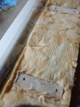
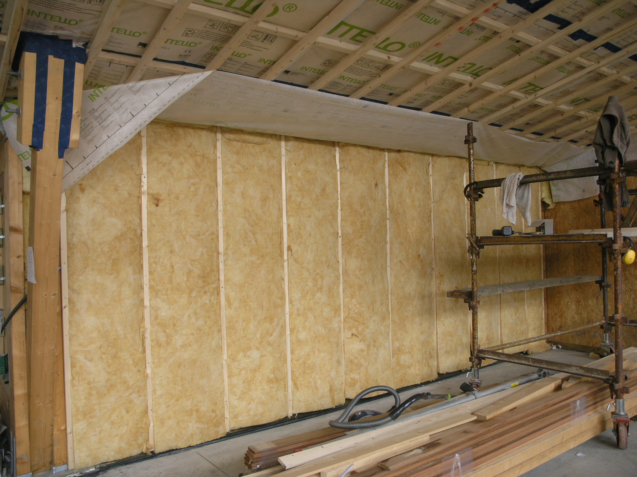
The image below is the RWA45 rockwook installation before the airtight membrane was installed. The wooden strips on the window sill are there to support the sill board. I kept them away from the window frame in order to decrease the thermal bridge. I now plan to use Rockwool RWA45 on all window sills as it performs better at not absorbing water as seen on a previous blog.
Thermal Bridge Build Up
The next image shows the finish layer of battens over the membrane.
Batten Finish Detail
The window (below) which was installed in the structural frame of the building (I purchased the glazing without the frame 2.4mx.9m) provides light and solar gain.Small lengths of floor board OSB were cut to size in order to build up the insulation and provide a base for the plasterboard finish.
Insulation is placed up against the glass and I plan to place a timber bead around the edge . Plasterboard will then finish the detail.
The finished (near finished) wall looks like this below.
I recently came across a few videos from America on the subject of building physics. They may help the self builder when trying to figure the wall system, roof design or insulation to use.
The videos are presented by Joseph Lstiburek who outlines the do’s and dont’s in a very direct manner. He is the founder of Building Science Corporation.
In the videos he references the American method of describing heat loss which is the R value (resistance to heat loss per inch- a higher number is better) while in Europe we mainly use the U value (ease in which heat travels through an object-a lower number is better but it includes boundary air films). The Rvalue is the thickness of the insulation divided by the K value or in the examples presented by Joseph Lstiburek the R value of 2 of the Irish building is approximately equivalent to a U value of 0.5.
This video starts with the progress for insulating buildings in 1000 years (starting with an Irish Church) and covers the perfect wall, roof and slab and the importance of designing buildings for the climate they are situated in.
Video (Below)
Commercial Thermal Bridging , LEED Building Problems, Water problems.
Physics Discussed (2nd law of thermodynamics)
Heat flow is from warm to cold
Moisture flow is from warm to cold
Moisture flow is from more to less
Air flow is from a higher pressure to a lower pressure
Gravity acts down
Quality Assurance-Figuring out what the right thing to do is
Quality Control– Executing it
The building layer order of importance for a wall, roof and slab and the importance of continuity between the layers as shown below in order of importance.
Water control layer
Air control layer
Vapour control
Thermal control
The 500 year wall-Keep the water out of it. Allow the vapour to get out from the inside or outside if it gets in. Keep the air out of the wall from the outside and inside. Put all the thermal layers on the outside and put the cladding on the outside.
He also analyses the LEED energy standard.
To Vent or not to Vent (Roofs-cold, warm and SIPS)
This video covers venting and airtightness of SIP roofs.
What happens when one uses a white roof membrane versus a black one.
Building Enclosures
Why increasing insulation is a game changer in the future . Moisture and durability issues that lie ahead because of extra insulation.
For the internal wall build up I am using a double batten wall system. This wall system allows one to easily install services. In a previous experiment on building a workshop (used as a means to experiment on a small building before commencing the house) I installed a single row of horizontal battens on the OSB board. This made it very difficult to run services that need to run vertically. I had to install metal protecting plates and cut notches in the wood in order to ensure that I did not damage wiring due to the final layer of plasterboard screw fixing.
When one uses a counter batten system it facilitates running services such as power, lighting, phone, internet, alarm etc without the risk of screw damage. This system also helps to reduce the cost of installing these services (see the image of a cable behind the batten below).
One can make use of a wall system like this if a soft insulation such as cellulose or fiberglass is behind the final batten which will support the plasterboard finish.
A row of battens run vertically behind the membrane in order to facilitate running services.
When working at ceiling level one may need to use a counter batten system in order to allow for recessed lighting otherwise it will mean installing special electrical enclosures cut into the airtight membrane. I have installed counter battens to a depth of approximately 90mm in the living and kitchen areas for LED downlights (see the previous post link on the 26/04/2015). In the bedroom areas I will only use a single batten system in order to install hanging pendent fittings.
Floor Level Insulation.
At floor level I installed Rockwool insulation for two reasons -one was to minimise the thermal bridging (heat loss around the wooden sole plate that the timber wall sits on) and the second reason was to minimise the damage to the insulation if there was a water leak.
I carried out a test where I placed 50mm of Rockwool RWA45 (product in the left bowl) and Metac (fiberglass-product in the right bowl below) in water in order to see what would happen if there was a leak. The Rockwool absorbs very little water but the fiberglass sank and became completely saturated and would possibly never dry out. Both insulation’s were submerged initially and then left for the duration of the test.
Rockwool versus Fibreglass for water damage.
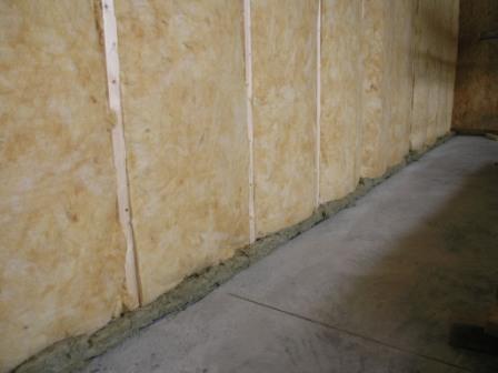
Below is an image of the Rockwool installed at floor level under the fibreglass in order to minimise the risk of insulation damage at floor level and minimise thermal bridging.
Rockwool Installed at Floor Level (green colour)
Airtight Membrane Installation
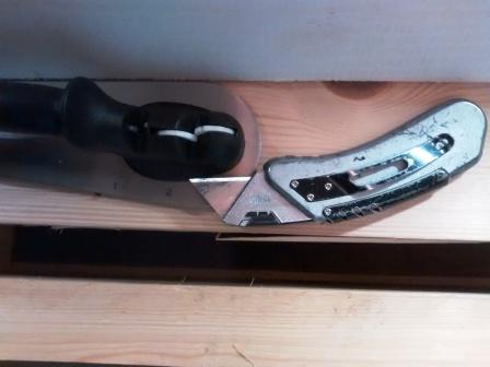
When installing the airtight membrane I was surprised how quickly the knife goes blunt. Rather than using the disposable knives and blades I now use a sharpener with the knife.
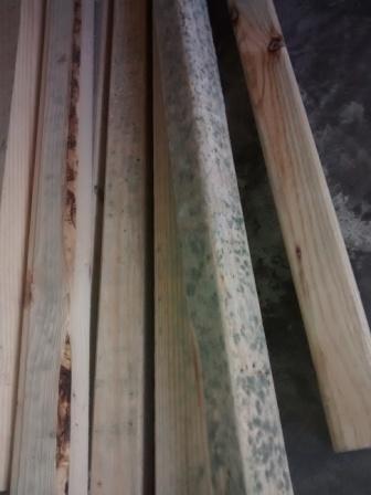
An item I feel worth monitoring is the supply of wood for internal use (untreated wood –no preservative used ). By monitoring I mean the moisture content. For example I received battens for the ceiling fixing of plasterboard. Some batches after 2 weeks grew mould. It was luck and the fact that I was not ready to install it that averted a real problem if it had been nailed to the rafters.
Mold on wood supplied
I did comment mentally to myself when I was carrying it into the house that some pieces were much heavier than others but that experience did not cause alarm. A symptom that I now know is that they were wet and this has a consequence.
In order to monitor the moisture content of dry wood supplied by building providers on site for the likes of battens that are used to secure plasterboard I will from now on use a moisture meter. When my supply was delivered I did not have a wood moisture meter at hand (they cost 20 to 30 euros). I do now . Even though the wood was purchased and supplied as definitely dry . Once I had it stacked indoors certain batches were obviously not as promised as mould started to appear within two weeks. The lesson going forward is have a moisture meter at hand. Test it while still on the lorry and send it back to the builder providers if the moisture levels are too high.
I have started preparing the internal walls for more insulation, air-tightness and the service cavity .
First Wall with 50MM Metac insulation between vertical battens
There appear to be no hard and fast rules on mounting the battens and counter battens . Below are the Gyproc guidlines:
“Horizontal application of plasterboard on walls is generally recommended because it: • Reduces joints by up to 25%. • Provides a stronger wall. • Reduces the possibility of unacceptable light reflections around joints. • Joints are at a more convenient height for finishing.
However, the orientation should be chosen so that – any critical light falls along the recessed joints; the number of butt joints is minimised; a single sheet may be fixed vertically where it covers the whole wall. Nogging is not required behind recessed edge joints in horizontal applications. Partitioning fixed to steel framing in commercial applications is typically sheeted vertically. The lower edge of wall sheets is to be kept a minimum 6mm above the finished floor level. Ceiling sheets are to be installed with the long edge at right angles to the direction of the joists/main support members.”
The important factor is batten spacing . A good spacing it apears is 400mm for the plaster board. I am installing the first row of battens vertically at 600 centres. These will carry the next row of battens for the plaster board at 400 centres. I am placing the final row of battens horizontally in order to facilitate wiring and services. Fixing the plasterboard with screws appears to be better than using nails (Nº6 Type ‘W’ for timber framing a different screw type is required for other systems.)
Wall Membrane and Airtight Layer with Battens
I used screws and serrated nails on the vertical battens. This layer of vertical battens will hold the 50mm metac insulation (see above and below). Next will be the airtight membrane followed by the horizontal battens. I will be placing 15 mm plaster board on the inside walls and ceiling and I am considering some other suitable board like a magnesium board (Mgo).
All the north facing walls will have cupboards/wardrobes placed in front of them. It allows me to practise knowing that they will not be seen again. I am also considering mounting the plaster board vertically on these walls as it will take one sheet exactly (2.4metre high).
Rockwool at Floor Level to minimise thermal bridging
Service Cavity
A small length of the lower floor section in the kitchen will have a service route specifically for pipes and wiring behind the skirting board. (I want some way of accessing these in the future without taking the wall apart .)
Insulation at floor level
At the floor level where the sole plate sits on the structural ring beam I am placing rockwool in order to reduce the heat loss (thermal bridge). It appears that rockwool has superior fire resistance-I must do a test this week and see for myself.
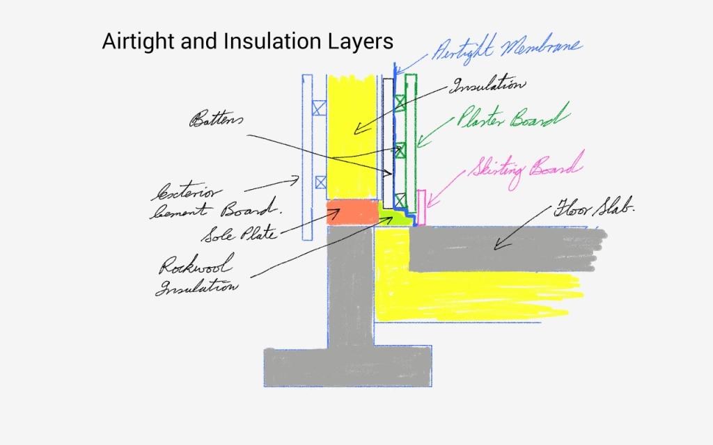
Wall Layers with Insulation
Above is a sketch of the wall build showing the basic components. For passive house certification I need to calculate the thermal bridge losses (linear heat loss) at this floor/wall junction. If I did not apply the rockwool insulation I would have significant heat losses and possibly condensation issues. I will calculate the thermal bridge losses using the free Therm software. It will show the real performance heat losses and condensation risks if any.
Having lived in an house that had single glazing and was draughty, I only realised how inefficient the ventilation was when I purchased a Carbon Dioxide meter (CO2) for the old house. This meter measures the amount of carbon dioxide in a room (as we all exhale CO2). The bottom line is that a level below 1000ppm (part per million) is taken as a healthy starting point. Another factor that is not healthy is Volatile Organic Compounds (VOCs) these are the chemicals, gases given off by furniture, paints, floor coverings, household cleaning agents etc. When one reads the possible health effects from VOCs it becomes clear that one needs to reduce these. See for example http://www.epa.gov/iaq/voc.html
In our last home what was amazing was how little oxygen we were getting especially when asleep (and in turn high VOCs). Within an half an hour the meter would alarm that the levels of oxygen (fresh air) were low.
What I used to do in the old house is determine if there was a wind blowing or a storm due. This then entailed adjusting the window opening to a minimum in order to ensure that we would get some level of oxygen. If there was no wind blowing outside then I would open the window to approximately 75 mm (The horizontal window was over a meter and a half long) and leave the bedroom door open for some cross ventilation through the house.
I think it is now widely accepted that holes in the wall or opening windows does not work for fresh air and a healthy environment. The only way that appears to work is to blow fresh air in / suck stale air out.
CO2 Meters
CO2 meters for some reason are expensive. The unit I purchased was over €300 a few years ago. I came across a more affordable unit recently on ebay for approximately €100 (allow for customs and excise) that also has a data logger (records the information over time). I feel it is well worth investing in one of these as the true quality of air in a house can only be believed when the CO2 levels are measured.
One seller on ebay was perfectprimetechnology . If one types in the word co2 at their store it should be easy to find or in any other store.
Carbon Dioxide CO2 Meter
While there is no direct link between VOCs and CO2 I have read that if one is breathing air in a room with high CO2 levels it gives a good indication that the VOC levels are also high.
Going Forward
In the new house we plan to use controlled ventilation which will supply fresh air and in turn recover some of the heat blown out of the house . It is a mechanical system called a Heat Recovery Ventilation Unit (HRV). I do not know why they don’t call it a fresh air unit as this factor has to be more important than recovering heat. In order for this fresh air supply system to work one has to control all drafts in the house as one does not want to be drawing air in around windows and doors and hope that the fresh air ends up in the correct room. This can only be achieved by eliminating drafts by sealing the building in an air tight membrane/system and blowing fresh air in and extracting stale air out using two ducts.
In order to carry out airtightness in a home one appears to have a few options -On a block house this is achieved by internal plastering (and some preparatory work) or for a wooden frame house one can use a membrane or take a chance on using OSB (Oriented Strand Board). Even a block house will still need air tight membranes on some structural details.
Another reason for using this special air tight system is to control moisture generated in the house from showers, cooking, drying clothes etc. This moisture can have a detrimental effect on the building fabric and reduce the insulation levels and in a worse case scenario lead to mould growth. I feel the mould issue is going to be a health issue for generations to come where insulation is added ad hoc to dwellings without a proper design using building physics. I am not aware of any building physicists in Ireland guiding the construction industry. A worrying trend I am hearing of is cases where the consumer believed that adding insulation was a good thing not expecting the creation of mould and health issues for themselves.
The Airtight Target for a Passive house
In order to control the ventilation and heat loss the passive house standard requires less than 0.6 air changes per hour at their test pressure. The best analogy I could find for this figure was at the passivhaus.org.uk web site. One must achieve no holes or less than one 18 mm hole for every 5 m2 of the building envelope.
Airtight Standard Passive House
Practical Experience of the first steps in airtightness
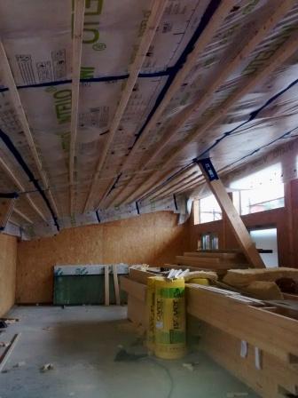
As I was installing counter battens on the ceiling in front of the airtight membrane I know from experience I missed the rafters in 3 locations in the roof. I am using serrated nails with a nail air gun. Once these nails are fired they are almost impossible to remove.
Serrated Nails
The strategy is not to try and remove them as this would leave a hole other than a nail in a hole behind the batten.
Installing battens on the ceiling
Another factor is to ensure that the insulation does not sag below the rafters before the airtight membrane is installed.
When one is laying out the membrane one needs to work in a triangle when stapling. For example staple 3 metres or more forward on one side and then find the centre of the other side and staple from this point to either side. Ensure that stainless steel staples are used as there is very little in the price difference.


 Wall Layers with Insulation