Self Build the plan-Solar PV
The plan is to have all the outdoor lighting (Using LED -Light Emitting Diodes) operate from a 12 volt recycled car battery and recharged by a solar PV panel. The lights will be controlled by the in-built timer in the MPPT charger. This will keep the cable cost to a minimum (small cable size) and keep the voltage low enough to be safe in a garden environment (when digging and planting).
Parts Required
Below is the CIS thin-film solar PV Panel (copper indium gallium selenide ) I mounted on the shed roof.

I selected a 60 watt solar PV panel that was manufactured using CIS . This type of panel has a higher output voltage of 52 volts which work better with the charger I selected rather than the typical mono or poly crystalline cells of 30 volts . One needs to select a charger to suit the PV one buys. The panel was mounted on a 3 degree pitch facing south (see above) . During tests I found that this type of cell is more forgiving for shading and dirt (bird droppings mainly)-it maintains a consistent output power . For example when I partially shaded it with my hand it still outputs almost the same power. If one partially shades a monocrystiline /polycrystaline cell it will cause it to stop working as all the cells in the unit are wired in series.
Measuring the efficiency of the installation.
In order to check the efficiency I mounted a pyranometer at the same angle (top left of image) so that I could ensure that connections and charger were working correctly. One needs to know the input power in order to check the charger efficiency and that the system is working correctly.
The MPPT Battery Charger
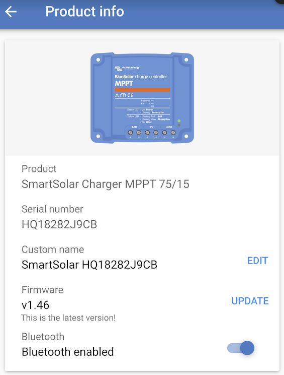 After reviewing products available I opted for the Victron SmartSolarCharger MPPT 75/15. This can charge a 12v or 24v battery system. When selecting a unit one needs an inbuilt MPPT which stands for Maximum Power Point Tracker. In Ireland and the UK this is important because of our natural cloudy weather which causes the solar panels to vary their output as the irradiance changes . What happens is that the solar panel’s internal resistance changes when the irradiance changes (sun shining on panel) -so the job of the MPPT charger is to change its load resistance as the solar panel’s internal resistance changes. When the load resistance matches the solar panel resistance then the maximum energy can be transferred to the load. If a charger did not have the MPPT then the efficiency of the complete system would be compromised. While there are different methods (algorithms) used to build MPPT units some are more efficient than others. Some of the different MPPT design options available are called perturb and observe , Incremental Conductance , short circuit current method etc., The idea of all these MPPT systems is to get the maximum power from the solar panel -some MPPT are low cost and others are more efficient in cloudy weather.

There are a number of advantages of the unit compared to others that I researched . It has charging algorithms for different battery types such as deep cycle and lithium ion. It has a bluetooth connection so that one can programme and monitor the output without other devices /connections being required. Another advantage is that it has a lighting timer that can automatically switch lights on and off at night or at dawn.
Some of the advertised benefits of the Victron MPPT unit are:

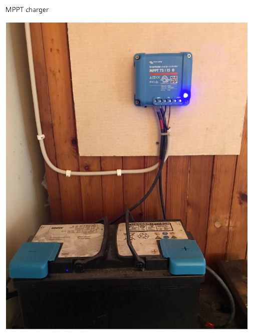
The Setup .
The setup is as follows . I plan to move the battery out of the shed as it is not best practise to have any battery system in a shed/garage/house because of the fire risk. The charger is mounted on a fire resistant material (Magnesium Board)
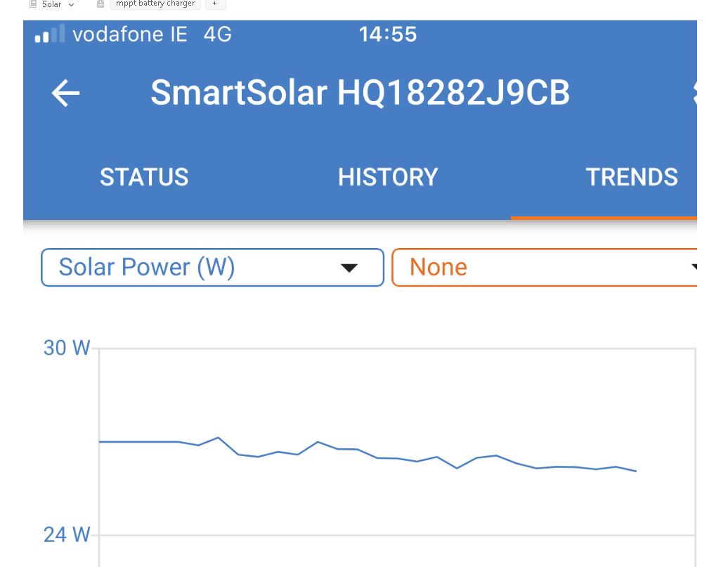
In order to access the data collected one logs on using the Bluetooth connection on your phone/tablet and the data is available. Below are different samples of the data available . The first indicates the solar power collected and the load usage. If the battery is fully charged it will take little or no power. If there is a load during the sunshine hours then the battery and solar panel will supply it.

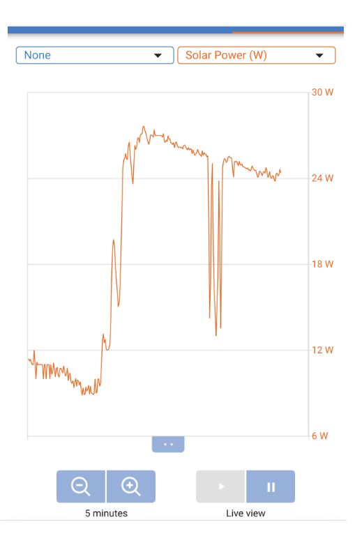
Below is a chart showing how the MPPT charger adjusts its output/load to follow the changes in the irradiance levels (power from the sun) per second .
As I am able to measure the input power using a pyranometer I built I was able to see that the system was working efficiently. The data below is the output power from the charge controller when the input power from the sun was 471 watts/m2. The CIS panel provides 60 watts output when the irradiance is 1000 watts/m2 at STD (Standard Test Conditions) . This would mean that if the input power was 500 watts/m2 then the output would be 30 watts/m2. The data from the charge controller indicates an output power of approximately 27 w/m2 for the 471 watt/m2 input power.