Category Archives: Sound Proofing

Heat Recovery Ventilation (HRV) Selection Part 3

Mounting of HRV Unit

Different HRV units have different mounting options. Some are floor only, wall only or ceiling or all three. Some units like the Airflow DV145 that I purchased can be mounted on the floor or wall while smaller Airflow units can be mounted on the ceiling, floor or wall. One needs to make sure that there is space underneath for the condensing water outlet.  If the unit is mounted on a wall make sure that vibrations do not interfere with noise sensitive rooms such as bedrooms. I mounted ours on a sound proof and isolated base and used other sound proof methods to isolate it from an adjacent room.

In the early stages of the build the fresh air inlet and stale air duct positions were selected with a spacing of over 2 metres. If the supply and exhaust ducts are too close this can interfere with the correct operation of the HRV unit. This entailed finding an HRV unit that would be flexible in the options available to simplify the space required for the main ducts and keep the runs as short as possible. The lengths of the supply and exhaust ducts play a big factor in the efficiency of the whole system. The Airflow unit comes in a right hand and left hand model. I found that different manufacturers have different duct layouts even though they have Right Hand and Left Hand models.

DATA from the HRV with the Post Heater On

HRV Data
HRV data February 2019 with post heater on

One can see from the above graph that with the winter sun I needed to switch off the heater and switch to summer bypass as the weather improved. The next plan is to automate the bypass mode when the solar irradiance level measured in W/m2 and temperature exceed a set value then the HRV would automatically switch over to the summer bypass mode as one is gaining solar heat. Update-2022-We found it easier and more economical to switch of the post heater permanently and set a base heating load of 1.35kw (200m house floor area) for the winter and manually switch on a 600 watt electric oil heater for days or evenings when the solar gain did not happen. In this way there will be days when one is not in the house and it is proving to be effective also. Also as the house id energy efficient the room heats up quickly. 

HRV Soundproofing

As the internal fans are to the rear of the unit I added a small amount of soundproofing as an experiment. I was able to reduce the db level from 49 db to 44 db. Each 3 db approximately equates to twice as loud or twice as quite depending on whether you are increasing or decreasing the level.

I mounted the unit in the hallway entrance so extra sound proofing was required. If one has a utility room then  extra sound proofing would not be necessary I feel.

HRV Efficiency

Following on from the previous blog I had a display panel built that calculates the HRV efficiency using the supply method and extract method by means of the Modbus data connection available in the HRV unit . In the Image below one can see S100 (Supply method for calculating efficiency) and the E 90 (Extract method ) as a percentage.  The supply method is the one typically used by manufacturers in brochures. The D  displays the difference .

HRV Efficiency
HRV

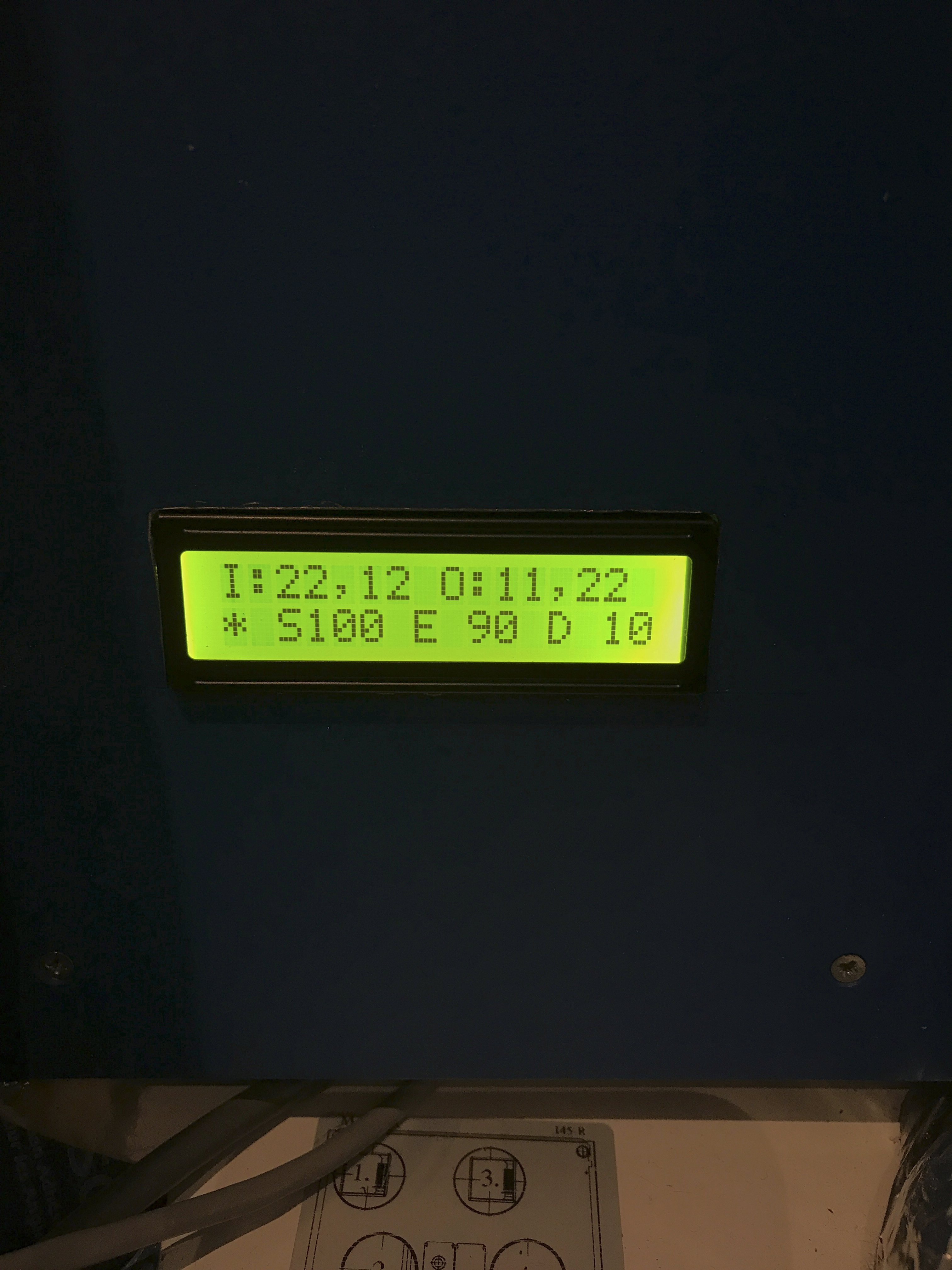
The top line displays the temperatures of the Inside air and the air leaving the house followed by the Outside air temperature and the supply air temperature to the house.  When the post heater is on the efficiency calculated with the supply method sometimes displays a number greater than 100% as the heater is built into the unit and mounted before the thermostat.  The extract method for calculating the efficiency is a closer representation of the real efficiency and it is similar to the passive house method (uses the same principle ). The extract method does not use the supply air temperature in the formulae.

Access for repair and maintenance.

Some HRV units require side panel access so ensure that you have enough space to get access to fans/ filters for cleaning and maintenance . The Airflow DV145 can be fully maintained from the front cover so it can be fitted in a corner space without restricting future access to internal parts. The filters are also maintained from the front panel.

Functions and Benefits

When selecting a unit- what was important to me that there was an integrated summer bypass function in the unit,  software control by a smartphone with data capture (a manual control panel-is an extra cost and another item that could fail) and an integrated post electric heater.  Airflow also sell a ground source heat pump option connection to the HRV which I did not purchase. For those installing a stove / fireplace one requires a Fireplace function built into the HRV . The Airflow DV145 has this function.

September 2018 performance.

HRV Software review and Control.
Example of HRV in use in our home.

Summer Bypass

The summer bypass function allows one to bypass the heat recovery function during warm weather or reduce winter sun peaks (when the sun is low on the horizon). The way this works is to bring the air outside directly through the ducts in order to reduce the internal temperature at night or during the day. One can see from the image above on the 28 and 29th of September I forced the HRV unit to summer bypass during the day to keep the temperate under control with the winter sun. No heating had been switched on for the month of September and the night temperature outside has hit the lowest in the same month of 2 degrees.

The Airflow unit is software controlled by means of your phone or your personal computer . This helps keep the HRV cost down, gives remote control and it provides data for analysis. The physical manual control panels in general cost €200 or more.

The post heater in the Airflow DV145 unit has a PWM (pulse width modulation) heating element control which means that it can control the switching of the heater within a fine tolerance for heating the air rather than just switching the heater On and Off.  The reason I installed this was really to provide a back up option to the main house heating system (approximately €200 extra).

House Heating System

The house heating is currently designed around two storage heaters of 1.7 kw each to heat the house using off peak electricity and operate for 7 hours a day. I picked up one unit for free and the other unit cost €70.  I suppose one could say that the total capital cost of the heating system was €270 when one adds the HRV post heater.

For the month of October one of these heaters was switched on for 14 days.  The post heater also improves the frost protection functionality within the HRV and helps maintain a heating level of 21 degrees Celsius throughout the house.

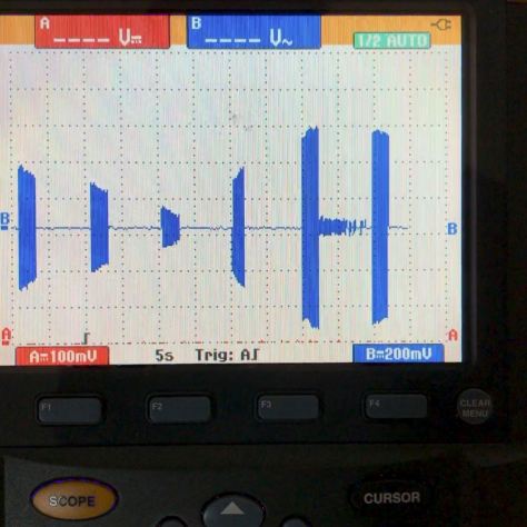
Below is an example of how the HRV switches on different heating loads in the post heater while maintaining a set temperature . The time interval below is over 60 seconds (full screen view) and the heater appears to adjust the power output required continuously to maintain the set temperature.

Post Heater HRV
Post Heater being switched on and off approximately six times in a minute with different heating outputs.

Duct work for primary supply and extract

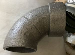
I selected an insulated 210mm EPS duct for the extract pipe as this duct carries the coldest air from the HRV unit .

Supply and Connecting Manifold Ducts

There are a number of options. My understanding is that the larger duct systems such as 150mm feeding multiple rooms with silencers is the best option if one can accommodate this in the build early on and find a good designer. I opted for the 91mm semi rigid ducts using a manifold system from https://www.fraenkische.com and I am very happy with the low noise level and amount of air being delivered throughout the house. I use a co2 sensor to monitor how the flow rates are working in different rooms.

Hiding Ductwork

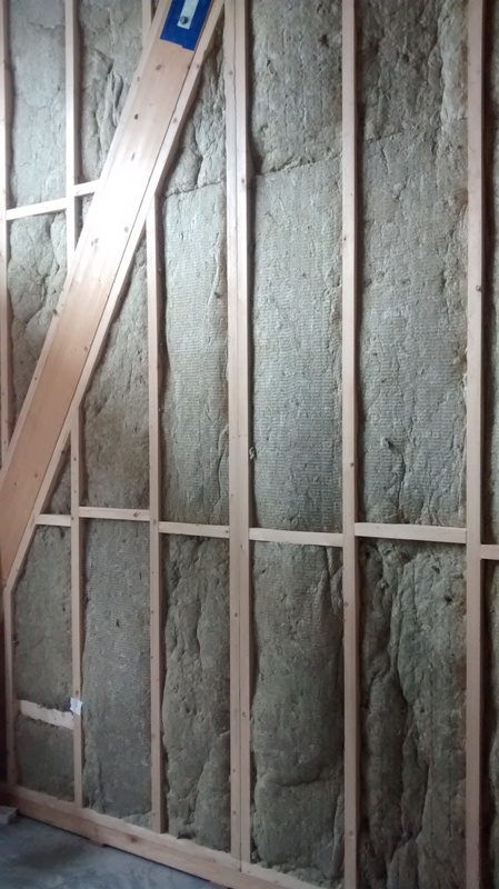
When one is designing a house to the passive house standard or installing an HRV unit in an energy efficient /airtight house one can reduce the cost on the system if one plans the service routes of the ducts early on and selects particular joist types. It is expensive to batten and counter batten to hide the ducts afterwards as one needs to try and keep the duct-work within the airtight envelope.

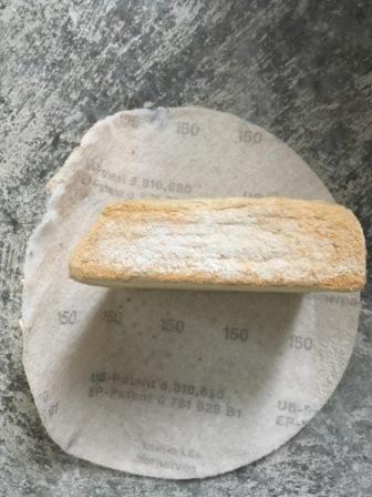
I opted for the manifold system using the largest semi rigid ducts I could find. These were the Fraenkische-profi-air classic pipe with an internal diameter of 78mm and outside diameter of 91mm. The larger the duct the lower the air friction and noise when delivering air to rooms such as bedrooms. These ducts are also anti-static and low emission.

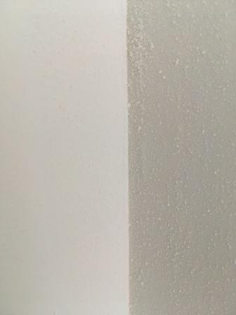
Below are the choices I came across from the semi rigid range. The white duct is made by Fraenkische.

Connection ducts from Manifold to HRV.

For the ducts that connect between the main HRV unit and the manifold I used an insulated flexible sound reducing duct (as seen below).  This is made up of an inner foil with sound reducing properties, next an airtight plastic membrane and then insulation followed by another layer of foil. The inner rim is re-enforced with a steel wire to provide rigidity.  It is time consuming connecting this up but it appears to have done its job.

HRV Duct
HRV ductwork

Contact Details:      seamus.sheehy.selfbuild@gmail.com

Heat Recovery Ventilation (HRV) Selection- Part 1

HRV OPTIONS

There are two types of HRV units that I came across -Heat (HRV) or Energy (ERV). The ERV is used principally for recovering humidity  and heat. I selected a HRV unit,

Size Matters

When selecting a HRV unit it appears that one of the biggest mistakes is to select a unit that is too small but still satisfies the current regulations. What appears to happen in the competitive world of quotations is that a unit that just ticks the box comes in as the best price.

In selecting a unit for our home I selected a unit that has a manufacturers capacity of 542m3/h where the floor area of our house is 205 m2. Currently the unit is running at 31% of its capacity and it is maintaining a CO2 (Carbon Dioxide) level of around 700 ppm when the four of us occupy it . I use a stand alone CO2 sensor to measure the CO2 in different rooms. (I have not commissioned the unit yet as the internal doors/glazing are not installed).  

Another advantage of selecting a larger unit is that it can run more efficiently at lower speeds and generates less noise through the ducts or from the unit itself.

Some of the options from the manufacturer Airflow (my unit is the third from the right).

HRV passive house
A choice from one particular manufacturer.

September 2018 performance (with no heating switched on yet).

The graph below gives an idea of how the HRV works when managing heat from the house and supplying fresh air. For the coldest days of the year so far (2 degrees at night-in September) I put the unit into summer bypass mode the next morning (take in outside air directly and pump it around the house) because the sun was shining that day. The winter sun is lower in the sky so solar gain increases in the winter (when the sun shines). The house is made of timber/glulam construction. The main thermal mass is the concrete floor at the moment soon to be covered by a 32 mm thick wooden floor so the response times of house I suspect will change. The floor and wall temperatures are approximately 22 degrees Celsius.

HRV Software review and Control.

Example above of HRV in use in our home.

Sample Data in our home using Google Fusion to visualise the HRV data for a week in October. (see link below)

  • One can select the chart tab and visualise the graph.
  • Use the bottom graph to zoom in.
  • The data is from the 21 October to the 28 October 2018.
  • One storage heater rated at 1.7kwh was used for 5.5 hours a day off peak.
  • The storage heater was switched off for one day on the 23rd October.
  • The graph starts at midnight on the 21 October.
  • Each ref reading is every 10 minutes.
  • The CO2 reading vary between 480ppm and 700ppm when fully occupied.

https://www.google.com/fusiontables/DataSource?docid=14U8eXcMzhritW7dQTPSuBEIYNhyDcayGJUlnuLyi

Filters

All HRV units contain a maintainable part called filters. They have a number of functions.

  • Clean the air being pumped into the house, and
  • Keep the internal components such as fans, ducts and HRV housing clean.

One typically finds one coarse filter and one fine filter on the air supply into the house and a coarse filter on the extract air from the house before the extract fan. The coarse filter is typically a G4 and the fine filter is a F7 (Pollen filter). I installed a 400mm x 400mm  G4 coarse filter at the duct inlet so that I could keep the main supply duct clean. It is a bit more effort to maintain this but it will hopefully minimise the maintenance of the duct.

To be continued………


Plumbing Update

Water Switch On.

I finally switched on the water supply to the house and then checked the compression connections on the gravity based system for leaks. The reason for using the gravity based system was to keep everything as simple as possible,  consume the lowest amount of energy and have a system that would be low in maintenance cost.  All the joint connections were brass compression fittings and I used a pipe called  “qual-pex” .  I insulated the cold and  hot water pipes for both the rainwater and the calorifier tank.

Gravity Tank 

I installed a  separate gravity tank for the toilets that will be fed from the rainwater tank in the garden eventually. I need to design a control unit to pump rainwater when required and operate from the mains to flush out the gravity tank at regular intervals. At the moment it is connected to the fresh water supply for testing.  This tank was mounted 2.71 metres above floor level.  Nylon washers were placed inside and outside of the tank brass connections fittings.

Storage Tank Connections


What worked for me in relation to the toilets was an 1/2 inch pipe that ran a distance of 15 metres approximately with a storage tank base to floor height of 2.71 meters and this enabled the cistern to fill in approximately 1 minute 45 seconds.

Lessons Learned

  • When tightening compression fittings- a good bit of advice is always leave room for an extra turn on the thread. In this way if there is a leak one can tighten the compression joint further.
  • On the calorifier connections use Jet Blue Plus paste or similar paste and check it is suitable for potable water.
  • The longest run was approximately 20 meters of 1/2 qual-pex and this  supplies enough pressure for a “natural” water flow at the furthest away sink outlet-I also removed the filter in the outlet of the tap to further increase the water flow.
  • Certain isolation On-Off valves have bore diameters that are smaller than the diameter of the pipe bore further reducing the capacity of the water flow. Visually check before purchase.
  • Check that the taps and shower fittings are designed for a gravity system. I used a tap that had a minimum operating pressure of 0.1 bar from the Grohe range (1 metre height of water is = 0.1 bar).
  • I was unaware of what an air lock can look like . In one case no water flowed and in another case I had a constant trickle of water with no air gurgling. To get rid of the air lock I used a small 5 litre pressure sprayer with a silicone hose on the end.Pressure Sprayer


  • Use copper inserts instead of nylon on “qual-pex” when trying to get gravity to work in your favour . They have a wider bore (see below).
Qual-Pex Inserts Copper and Plastic
Copper versus Plastic Inserts


Toilet Cistern

As most of the inlet valves on toilet cisterns are now designed for high pressure they come with a restriction devices and sometimes a filter. For use on the gravity system I removed these.

I plan to filter the water at the feed end of the water supply.  Both the toilet storage tank and the calorifier storage tank (supply’s the hot water) are within the thermal envelope. This means that the tanks will not freeze but this brings other issues to be dealt with, such as noise from filling and potential condensation. I installed rockwool insulation around the tank to minimise temperature differences of the indoor air and reduce the noise of water filling the tank as I have no attic space.

The original toilet had a bottom inlet valve made with plastic threads which proved difficult to install.

Cistern Inlet Valve


I did have problems with the original cistern valve where I cross threaded the plastic connection (which resulted in a leak) as one finds that space is limited under a toilet/cistern (see below).

Toilet Cistern with Penny valve for turning water off and on at the toilet.
Toilet Cistern Connection


Another problem I had was I could not get it to operate correctly from the gravity tank. To solve the above I replaced the inlet valve with a Jollyfill telescopic Wirquin brass inlet valve and removed the high pressure device.

Wirquin Bottom Inlet Valve


When I installed  the inlet valve the connection leaked between the rubber seal and cistern. I removed it and placed silicone above the rubber seal. The silicone cured the problem.

Shower

The gravity flow rate proved too low for the shower valve temperature control to work so plan B was acted on. I installed a 1.5 Bar 250w pump to raise the flow rate.

It is a Salamander RP50PT pump (45.5 dBA) . It cost €200 including postage. I am impressed with the low non-intrusive noise it generates. It comes with small sound isolating pads. One can roughly equate a 3dBA increase with twice the loudness.

Another factor to take into account when selecting  and sizing a pump for one, two or three shower units is that the power usage approximately doubles when one selects a 0.5 bar increase for this range of pumps.  So If one is sizing for the use of 3 showers being on at the same time (using one 3 bar pump) and only one  shower is on then one will be using 1000 watts of power most of the time . I feel it is more energy efficient to install separate pumps and in this way one uses the least amount of energy most of the time and the pump will also be quieter as noise increases also with each 0.5 bar of pressure.

Shower Pump
Salamander


Plaster Board Finish

Wall Finishing and Fire Compartmentalisation

Sanding

The golden rule is-avoid sanding as much as possible by ensuring that the knife finish is smooth at the edges and as close to a final finish as possible.  If one had to do this manually with a sanding block and pole it would be a tough job.

Thankfully over the years people have been improving the tools. I was lucky enough that the builder loaned me his sanding machine.  I just needed a hoover to manage the dust which was picked up free on the free cycle web site. The sanding machine looks like the following:

Sanding Machine
Flex WS 702VEA

Even though the above Flex machine makes the job easier and faster it still is a physical job especially when working overhead.  The hoover was not designed for the above but it worked out OK once the bag and filters were cleaned regularly.

I would suggest safety glasses when working overhead and a face mask at all times.

Technique for Sanding Used

The joints had a second coat of plaster and then a touch up coat was used to remove any edges and at the same time look for and fix any imperfections on the butt finishes (where two boards are joined with no taper edge) or tapered edges. USG 3 Sheetrock (see previous blog) was used for the second and third touch up coat.   I would not recommend the Gyproc joint filler for the second and third coat as it is primarily used for the first coat and it does a great job. When dry the finish is very hard and it would be difficult to sand. There is a Gyproc pro finisher but I found the Sheetrock product very economical and easy to work with for the second and third coat compared to other options.

I used a 150 grit sand paper on the Flex machine and left it at speed 4.   I was expecting that the sand paper would get blocked up but this did not happen. I was advised and found it very important to sand the edges of the joints and ensure that one does not stay too long on the edges as the paper on the plaster board could be damaged.  A light sand in the centre of the joint is how I finished each joint.

Sanding Joint Filler
Edge Sanding of Plasterboard


I also found it necessary to manually inspect the wall after the electric sander as one is too far away from the wall with the sander to spot imperfections. I made up a hand sanding block for this with a wood fibre board angled to get into corners.

Home Made Sanding Block


The angled  wood fibre board worked out better for me than dedicated sanding blocks and I used a pre-used sanding disc from the electric sander.

Self Build
Wood Fibre Board as a sanding block.


Plasterboard Corners

I experimented with the wall corner finishes on whether a sharp edge or rounded corners worked out better. The sharp edges looked like that shown in the top image below and the rounded corner is the image below that. If I was doing it all again I would use the rounded corners as I feel it looks better.

Plasterboard corner finish straight edge. Note dust still on one wall.


Rounded Corner

Fire Compartmentalisation

Typically with internal wooden stud walls there may be gaps between rooms at floor level or vertically. For this reason one may want to ensure that fire compartmentalisation is addressed (a previous blog covered this in detail). In order to do this I have chosen a B1 rated fire foam for the floor gaps. It also has a secondary benefit of reducing sound travel between rooms at these gaps. The foam I used was Olive PU-476.  The price varies and the best value I found in Ireland was at National Seal Systems in Dublin. I also bought intumescent water based fire sealer for small gaps around the edges of the distribution board and vertical uprights where one partition  meets another.

Self Build


Acoustic and Fire Design

Fire and Acoustic Isolation

Having recently come across a best practice guide for Electrical installations and their effect on the fire performance of buildings I have decided to change  the approach to the fire/acoustic isolation between rooms. I will now install Rockwool flexi 50mm in the 100mm partition walls and Rockwool flexi 100mm in the 140mm partition walls .

Electrics before insulation
Partition before Insulation with Wiring
Rockwool
Partition wall with Rockwool installed

From an acoustic perspective I was advised that it is better to install the Rockwool in the centre of the partitions rather than touching one or other side of the plasterboard as this limits the sound transfer.

The Electrical Safety Council best practice guide deals with Electrical installations and their impact on the fire performance of Domestic premises at this link when one is building a home. A summary is as follows but the full document is worth reading for any self builder.

  • Fire containment in the event of a fire
  • The need to prevent fire from passing through holes in all elements whether solid or lightweight is addressed.
  • Electrical Equipment is identified that has a direct and significant influence on the fire performance of an element.
  • Partial Penetrations –those that reduce the fire performance of part of the wall/ceiling or floor.
    Full Penetrations-such as ducts and fans that go through both elements of a wall/ceiling/floor.


Internal Partitions and Soundproofing

Partitions

The internal partitions were recently installed.

Passsive House
Passive House Build

Solutions now need to be planned to minimise noise between some of the rooms. The effort one puts into this needs to be balanced with the fact that there will be a 10mm gap under the doors for the air to circulate when using heat recovery.  I might install a supply and extract outlet in the important rooms in order to minimise noise. How much noise will travel in these ducts is for another day.

Proposed Method

All the air gaps (wall to floor gaps, sockets, switches and service cavity) around the partitions need to be filled.

I will fill the ceiling and wall gaps of the service cavity with rockwool (see below).Perimiter Insulation

The method to reduce the noise I am considering for the walls is a product that uses a dampening material between two sheets of plasterboard. One of these products is Green glue and the other is Quietglue pro.  The solution appears to perform very well and I feel it is the simplest method. I plan to take  extra measures between the study and living room such as including rigid insulation (Rockwool RWA45 but I note the insulation costs €37 in Ireland and £13 in England (more research required) .

The performance values used to measure the sound proofing in America is called STC (Sound Transmission Class) and is measured in decibels (dB) against 16 different frequencies. If the sound level was 80dB in one room and the measured sound level in the other room had a  STC of 37dB the sound reduction would have a figure of STC 43.

STC only calculates the dB levels down to a frequency of 125 Hz. One needs to be aware that low frequency sound can exist from drums , traffic and an additional solution may be required.

The performance test data of the Green Glue can be found here

If one was to use one layer of green glue with an extra sheet of plasterboard one would achieve a STC value of 43 for a 4 inch wooden stud wall with 24 inch centres.

If one was to use 4 inch block this would achieve a STC of 44.

Filling a standard 4 inch wooden stud wall (with 16 inch stud spacings) with fibreglass and using plasterboard on each side achieves a STC of around 39. If one increased the stud spacing to 24 inches and filled it with insulation then the STC value would be 46.

If one was to leave out the insulation on a standard wooden stud wall one would achieve a STC value of 34.

A good source of information on sound proofing is at USG (Gypsum)

Robust Airtightness

In locations where the partitions meet the airtight membrane I am using Solitex Plus (see below -blue material). If one used only the airtight membrane it can easily be damaged.

Passive house
Solitex Plus