November 3rd to December 3rd -2025-The total power consumption to heat the house excluding water heating was 184.11 KWh which equates to approximately 6 kwh per day to heat the house to the slightly higher temperature of 22 degrees in the main living area and the dining/kitchen room to 24 degrees 24 hours a day.
Solar PV generated November =60kwh from the 3kw pv system.
December 3rd to January 3rd -2026- The total power consumption to heat the house excluding water heating was 232 KWh which equates to approximately 7.73 kwh per day to heat the house to a temperature of 22 degrees in the main living area and the dining/kitchen room to 23 degrees 24 hours a day. The total for the space heating season is 416kwh to date.
Solar PV generated December =32kwh from 3kw pv system.
January 3rd to February 3rd -2026- The total power consumption to heat the house excluding water heating was 286 KWh which equates to approximately 9.53 kwh per day to heat the house to a temperature of 22 degrees in the main living area and the dining/kitchen room to 23 degrees 24 hours a day.
Solar PV -from January 3rd to February 3rd the 3kw system generated 45.4KWh which equates to about 17% of the energy for heating the house if all the solar was used for home heating .
Updated on the 5th March -2026
February 3rd to March 3rd-2026- The total power consumption to heat the house excluding water heating was 205 KWh which equates to approximately 6.8kwh per day to heat the house to a temperature of 22 degrees in the main living area and the dining/kitchen room to 23 degrees 24 hours a day.
Solar PV -from February 3rd to March 3rd the 3kw system generated 87.5KWh which equates to about 40% of the energy to heat the house if all the solar was used for home heating . Half of the solar PV installation is pointed North at an angle of 12 degrees. The other half of the PV system is mounted flat (3 degress) , south and shaded .
Updated on the 3th April -2026
March 3rd to April 3rd-2026- The total power consumption to heat the house excluding water heating was 147 KWh which equates to approximately 4.9kwh per day to heat the house to the slightly higher temperature of 22 degrees in the main living area and the dining/kitchen room to 23 degrees 24 hours a day.
Solar PV -from March 3rd to April 3rd the 3kw system generated 253kWh which was greater than that to heat the house if all the solar was used for home heating . Half of the solar PV installation is pointed North at an angle of 12 degrees. The other half of the PV system is mounted flat (3 degress) , south and shaded .
Updated on the 3th May -2026
April 3rd to May 3rd-2026- The total power consumption to heat the house excluding water heating was 14KWh ( a significant reduction) which equates to approximately 0.46kwh per day to heat the house to a temperature of 22 degrees in the main living area and the dining/kitchen room to 23 degrees 24 hours a day. The air to air heat pump was mostly off as the winter solar gain took over in heating the house. At some stage I will add the daily temperature readings inside and outside the house to show the actual temperature changes.
Solar PV -from April 3rd to May 3rd the 3.6 kw system generated was 479 kWh which was greater than that to heat the house if all the solar was used for home heating . Half of the solar PV installation is pointed North at an angle of 12 degrees. The other half of the PV system is mounted flat (3 degress) , south and shaded . Two extra 300w panels were added using the enphase micro inverters system. 1.2 kw of the solar installation is shaded by a tree and shrubs early and late in the afternoon.
Background– As previously discussed we had used two storage heaters to heat the house. The capital cost of this heating system wa €70. The passive house standard requires a heating load of approximately 1 Kwh for every 100m2 on the coldest day of the year. With the increase in energy prices and the slow pace of global warming the off peak electricity costs have risen from below 9 cents to its current price of 19 cents. We then made the decission to install an air to air heat pump as shown below that would reduce the real cost to approximately 1/3 rd of what we use to heat the house. The unit cost approximately €700 to buy and approximately €1000 to install.
In this blog I will discuss the learnings from the use of one air to air heat pump to heat a 200m2 house designed with the PHPP software to the passive house standard. The location to install the internal and external unit is very important. What is not covered in the passive house standard I feel is the dampness in Ireland that penetrates the human body to the bone. The operating design temperature of the passive house is generaly 21 degrees celcius. We found we needed 22 degrees for the living room and 18 degrees approximtely for bedrooms. The kitchen/dining room temperature will be explained below.
How to deal with the Irish Weather
Thawing Out in Ireland -AI generated
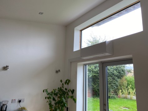
The other factor when one installs a central heating appliance whether it is a stove, an air to air heat pump or an electric fire in a passive house is I feel is to ensure more heat is available in one particular room to thaw out. This I feel is a good thing for the Irish climate because we found the constant temperature of 21 degrees one was slow to heat up when we came in from the cold. I feel one needs a stronger heat source to drive that initial dampness out of ones bones. We can all relate to standing in front of a fire to thaw oneself out, this can take the form of standing in front of a fire, a stove or an aditional heater. In our case we used the air to air heat pump by installing it in a selected room.
The location is important because the air to air heat pump does blow out warm air and this would be uncomfortable if it was installed in front of a seating area. Our selected location was the kitchen /dining room and aimed between two worktop islands in the kitchen that normally only has foot fall. In the dining room/kitchen I also installed two seperate air supply ducts (92mm each) with one extract duct. This also benefits in ditributing the heat throughout the house as more air is supplied into the kitchem/dining room rather than extracted. Most of the extract air ducts belonging to the Heat Recovery Ventilation (HRV) unit are also at the far end of corridors of each living space which means that air has to be drawn from the supply areas to the extract areas for ventilation.
The first room we go to if we encounter that outside cold damp Irish weather is the kitchen/dining room where the air to air heat pump is installed. The temperature in this room is around 24 degrees which is then dispersed to the rest of the house by the means outlined above. As it is a single storey house the heat does move around slowly with the help of the heat recovery unit. If it was a two storey dwelling with a better form factor then I would imagine the heat would rise to the bedroom areas easier if one wanted higher temperatures than what we use.
I also experimented with the extract and intake fan speed rates of the HRV as this affects the temperature of the house. If one increases the HRV ventilation rate higher than one needs for a healty air supply then more energy is used by the heat pump to keep the temperature at the levels required.
The other factor to take into account is that we found that if more doors are closed then the distribution of heat can be controlled in the house. For example when measuring the co2 rates at night in our bedrooms we found that we needed a higher air flow when more doors are closed around the house. What we found works is that if we reduce the HRV fan speed during the day (which reduces the heating load of the air to air heat pump) when people are using more of the house and increase the HRV at night because more doors are closed this works. So simply by closing and opening doors one can control the temperature of the house -for example if we leave the TV room door open during the day the heat enters that room. If one closes the door then the temperature drops to 1 to 2 degrees less than the rest of the house.
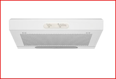
We also recently installed a simple electric hop extraction unit with a carbon filter that is not ducted to the outside to reduce cooking smells around the house because more air is supplied to the kitchen/dining room than extracted .
I think one also needs to have an extraction unit for air fryers as this is now more widley used than the hob to reduce the cooking smells being dispersed around the house. This will be a seperate project to be accommodated for when we install a new kitchen .
The performace for the Samsung 1.6 KW air to air heat pump over the month of November 2025 is as follows .
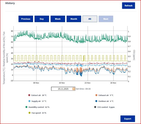
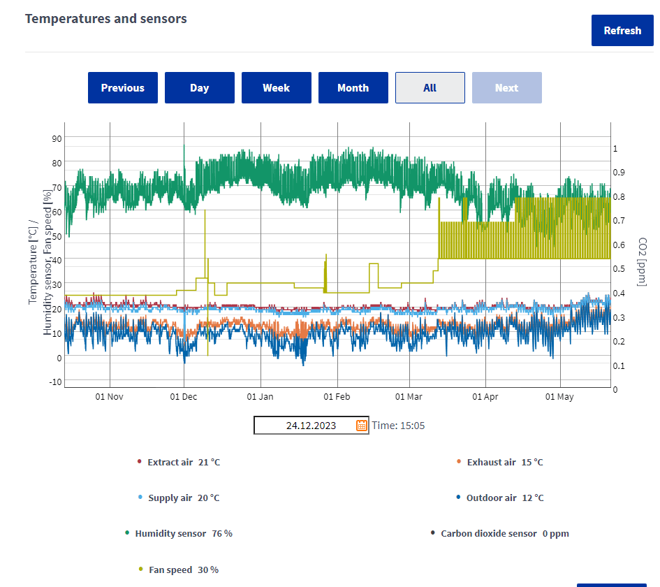
The electricity usage from the 3/11 to the 3/12 2025 was €1.60 a day when one takes into account the current night rate and day rate of 19 cents and 29 cents. The lowest outdoor temperature recorded was -1 degrees celcius . The total power consumption was 184.11 KWh which equates to approximately 6 kwh per day to heat the house to the slightly higher temperature of 22 degrees in the main living area and the dining/kitchen room to 24 degrees 24 hours a day . Below is the plot of the air temperature recorded by the Airflow Adroit DV145 HRV unit I installed . The bedroom temperatures were approximately 18 to 19 degrees celcius.
HRV Data November to December 2025
SOLAR PV electricity offset
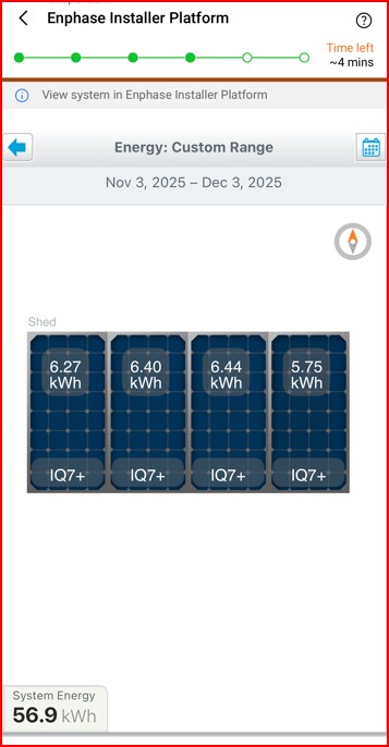
I have installed 3kw of solar PV panels and plan to add another two panels in the comming weeks. Solar PV panels can now be purchased for approximately €60 each (450watt). As I use the enphase micro invertor system the installation is easy to expand as discussed in another blog. The only disadvantage in our house is orientation as most of the solar panels are pointing north at 12 degrees while in order to maximise the solar gain of winter sun one needs 60 degrees panel orientation in a south-east direction. Even so for the month of November above 56.9 KWh of electricity was generated. If I was to offset the electricity generated the cost of heating the house would drop to around €1.02 per day when using the day time electricity rate of 29 cents per kwh.
Group 1
CO2
I started recording the co2 readings this month in the hallway rather than in one particulat room. A new co2 unit has been ordered so that I can get seperate reading for different rooms. The co2 readings varied from 672ppm to 1000 ppm in the hallway as the house is open plan with no doors in the kitchen/dining , the living room or onto the hallway.
Air to Air heat pump
For all the above measurements I set the heat pump to 75% capacity and a fan rate of 2 (4 available to adjust the air flow speed) which equates to 50% . My undertanding is that if one can set the heat pumpl rating to a lower output capacity this extends the life of the heat pump. Currently the temperature setting on the heat pump is set to 23 degrees in the kitchen/dining room.
Air to water cylinder-The next plan is to install in the kithen/dining room a small air to water cylinder to reduce the cost of heating water. Some of these units have a seperate coil where one can connect solar hot water panels with drainback or vacuum tubes to get free water heating in the summer months. We currently heat the water on a night time electricity rate of 19 cents. While this electric element is a simple low cost method and easy to maintain with the lowest installation cost -the long term cost of electricity is only going up. The plan is to reduce this rate to a third of the price with a unit like that shown below.
Other advantages of an Air to Air heat pump compared to air to water heat pumps is the ability to supply heating when it is required and quickly switch off the unit if there is solar gain in the winter (the sun has been known to shine in Ireland in the winter months). The air to water heat pump will have a slower response time through the concrete floor.
Installation-The installation of the internal and external unit needs careful design/planning. Both need to be considered at the same time. The factors to consider for the external (Inverter) unit is a location that is not subjected to high winds (higher winds will mean lower temperatures during the heating season and reduced efficiency), mounting the external unit at least 100mm (I used 300mm) from the rear wall (restricting air increases the energy usage). There should be no air flow restrictions in front of the unit either. Mount the unit on a secure and flat surface (the external inverter requires a flat surface so that compressors are balanced to reduce vibration). Vibration leads to lower reliability. The length of the pipework also needs to be considered and noise levels. The maximum noise level for our unit is 61db if on full power.
The external unit requires an electrical isolation switch and a condensation drain for the cooling season (it removes moisture from inside the house).
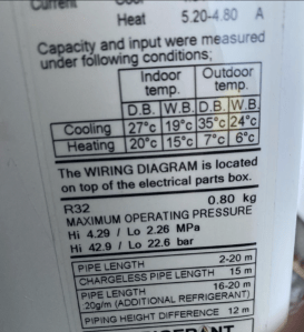
Power Consumption-The maximum power consumption of the external unit is 1.6kw with a typical power consumption of 1.08kw to produce up to 4kw of internal heating. Typically a passive house requires 1kw of internal heating for each 100m2 on the coldest day of the year . Our home is 200m2 so 2kw is required. The 4kw output power will allow more heat capacity if required. Most Air to Air heat pumps have an option to control the output power using the remote control. One can reduce the power to 50% or 75% of its rating. I will set ours to 50% for year 2 (2024-2025) which approximately equates to a max heat output of 2Kw on the coldest day of the year. This has the advantage for passive house builds of increasing the life of the Heat Pump compressor and ensuring the unit does not use more power than is required. It will also reduce the noise level by 4db (which equates to a reduction of noise by approximately half).
Typical Operation-The operating temperature range of the external inverter is –15 degrees to +24 degrees in the heating cycle. The typical internal heating temperatures achieved for 6 degrees and 7 degrees outside temperatures are shown below. Most heat pumps will also have an automatic defrost cycle when the external unit freezes over due to low outside temperatures. No heat will be delivered inside the home during this cycle and it only lasts a short period of time. If a house is designed with the passive house software (PHPP software) it could take a day or two for the temperature to drop significantly due to the highest air tightness standard in the world (0.6 ACH), quality control around the building fabric and designed to a performance standard.
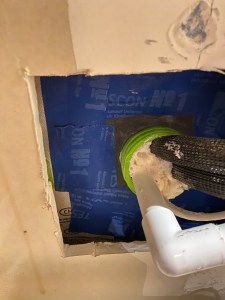
It is also important to mount the unit above ground level so that snow does not block the unit from functioning. A HO7RN-F (A rubber/Neoprene flexible cable) 4 core cable is required to connect the outside unit to the isolation switch (red switch shown below) which in turn requires another isolation switch inside that in turn controls both the inside and outside unit.
Cables and Ductwork-The cables and ductwork installation for a heat pump with a timber frame construction requires care during installation. When locating the cable and duct route through the wall use a narrow hollow pipe to find a path through the insulation and then drill through this pipe. If one uses a drill on its own with fibreglass insulation will wrap itself around the drill and leave thermal gaps in the wall and result in thermal bridges. The method I used is shown below. I used a rubber airtight gland to seal the larger duct. Ensure that this hole is mechanically sealed during the interim works from any rodents entering your build.
Power Usage-For year one of the installation I experimented with different settings -example using a high heating mode during off peak lower cost electricity and then returned to lower heat output during day. For year two I will set the unit at 50% of its output heating capacity and try an option called ECO mode which automatically reduces the temperature over time. For the last two weeks in this mode (October week 1 and 2) the unit used 20Kwh (€5 @ 0.25 cents per Kwh) to heat the house. The input power used by the air to air heat pump was approximately 300 watts when heat was required. The plan is to increase the number of solar PV panels to offset this 300 watts during daytime use. The power consumption varies as the external temperature changes. In the first year we used between 28Kwh per week up to a max of 50kwh during the first year of experimentation during the winter heating season. A power meter is now installed to record the daily/weekly and monthly power usage as shown below.
Below is the HRV (Heat Recovery Unit) temperature /humidity plot over the 2022-2023 winter period with the air to air heat pump. I reduced the HRV fan speed to minimise the amount of energy consumed in the winter time and increased it at the end of the winter season as shown below .
Internal Unit-The internal unit requires a height above floor level of 2.4 meters and at least 65mm clearance above the unit. In our installation there is approximately 1000mm clearance above the unit to allow the unit to blow air upwards to ensure a more balanced room temperature and air flow in the room. This is a built in function of this particular unit .
Further Experimentsand Research-I am also experimenting with a secondary heat distribution unit to improve heat flow around the living area of the house in year 2 in order to optimise the temperature differences one finds at ceiling height versus floor temperature.
Selection of a Low cost heating system for a passive house.
There are a number of options to heat a home when energy efficiency is designed into the build from day one. This statement is particularly true when one aims for the passive house performance standard using the PHPP (passive house planning package) software. When we moved into the house one will see from a previous blog that we started out with two storage heaters to heat the house with off-peak electricity with a capital cost of €70 (One storage heater was free and the other we paid €70 ).
Times have changed and the next energy crisis came along in 2022. We now have switched to a 1.6 kw air to air heat pump . These units are cheaper to run and more efficient than other types of heat pumps or heating systems. The other reason a dedicated home heating single unit was selected was to simplify maintenance. The hot water system is independent of the house heating.
One benefit of using an air to air heat pump to heat the house was the realisation that in Ireland when one returns home after being exposed to a damp cold climate it was difficult to thaw out quickly when the whole house temperature was 20/21 degree Celsius when using the storage heaters. By careful placement of the heat pump one room in the house is now at a higher temperature. This almost equates to a fireplace being available to help drive out the dampness one absorbed. We also noticed the room is used more frequently.
The room we selected was the kitchen/dining room. I feel it is important to ensure that the warm air the unit is blowing out does not interfere with the area one uses near or under the unit. This particular unit has an upward air circulation option that can limit this but we still installed it in an area that is not a functional working or sitting area.
To select the correct size of a heating source one needs to review the passive house PHPP software for your home. In principle the passive house standard selects the coldest day of the year for this calculation. In Ireland the PHPP software uses local climate data installed in the software to calculate the heating required for the house. This equates to approximately 1kw of heat for every 100m2 of floor area. As our home is 200m2 we needed 2 kw output on the coldest day of the year (similar to the power a toaster or hair-dryer uses for the coldest day).
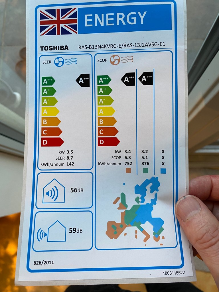
The Air to Air heat pump we used was the RAS-B13J3KVSG-E internal unit and the RAS-13J2AVSG-E1. These were one of the most efficient and economical units I could find. The price of the unit was around €600. Installation was another €1000 approximately. There are designer internal heat pumps options available from the same brand if one want to make the unit a design feature.
How the heat pump works -All heat pumps harness the natural heat energy present in the environment, air-to-air heat pumps can amplify the input power, resulting in a higher output. This is known as the Coefficient of Performance (COP), which measures the ratio of output power to input power. A higher COP indicates greater efficiency, and air-to-air heat pumps typically have a COP of 3-4, meaning they can produce 3-4 units of energy for every unit of electricity consumed. The air to air heat we installed has a SCOP of 6.3 and the designed heating load for the year is 752kw/h per annum. This approximately equates to €25 a month for a 7 month heating season @23 cents a kw/h. The letters SCOP is a seasonal calculation for the full heating season. In our unit the COP can produce 20 degrees inside if the temperature is 7 degrees outside.
There is also a function to cool the house with an air to air heat pump when global warming arrives in Ireland. Ireland missed the global warming cycle this year (2024) so we did not need to use this function.
Part 2 -Installation, performance and lessons learnt after 1 year of use…to be continued…
The plan is to have all the outdoor lighting (Using LED -Light Emitting Diodes) operate from a 12 volt recycled car battery and recharged by a solar PV panel. The lights will be controlled by the in-built timer in the MPPT charger. This will keep the cable cost to a minimum (small cable size) and keep the voltage low enough to be safe in a garden environment (when digging and planting).
Parts Required
Below is the CIS thin-film solar PV Panel (copper indium gallium selenide ) I mounted on the shed roof.
Solar Battery Charger
I selected a 60 watt solar PV panel that was manufactured using CIS . This type of panel has a higher output voltage of 52 volts which work better with the charger I selected rather than the typical mono or poly crystalline cells of 30 volts . One needs to select a charger to suit the PV one buys. The panel was mounted on a 3 degree pitch facing south (see above) . During tests I found that this type of cell is more forgiving for shading and dirt (bird droppings mainly)-it maintains a consistent output power . For example when I partially shaded it with my hand it still outputs almost the same power. If one partially shades a monocrystiline /polycrystaline cell it will cause it to stop working as all the cells in the unit are wired in series.
Measuring the efficiency of the installation.
In order to check the efficiency I mounted a pyranometer at the same angle (top left of image) so that I could ensure that connections and charger were working correctly. One needs to know the input power in order to check the charger efficiency and that the system is working correctly.
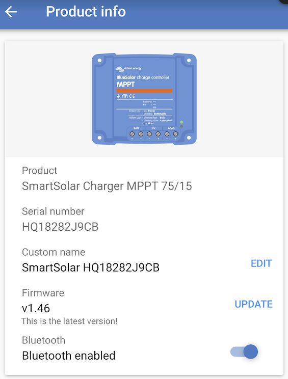
The MPPT Battery Charger
After reviewing products available I opted for the Victron SmartSolarCharger MPPT 75/15. This can charge a 12v or 24v battery system. When selecting a unit one needs an inbuilt MPPT which stands for Maximum Power Point Tracker. In Ireland and the UK this is important because of our natural cloudy weather which causes the solar panels to vary their output as the irradiance changes . What happens is that the solar panel’s internal resistance changes when the irradiance changes (sun shining on panel) -so the job of the MPPT charger is to change its load resistance as the solar panel’s internal resistance changes. When the load resistance matches the solar panel resistance then the maximum energy can be transferred to the load. If a charger did not have the MPPT then the efficiency of the complete system would be compromised. While there are different methods (algorithms) used to build MPPT units some are more efficient than others. Some of the different MPPT design options available are called perturb and observe , Incremental Conductance , short circuit current method etc., The idea of all these MPPT systems is to get the maximum power from the solar panel -some MPPT are low cost and others are more efficient in cloudy weather.
There are a number of advantages of the unit compared to others that I researched . It has charging algorithms for different battery types such as deep cycle and lithium ion. It has a bluetooth connection so that one can programme and monitor the output without other devices /connections being required. Another advantage is that it has a lighting timer that can automatically switch lights on and off at night or at dawn.
Some of the advertised benefits of the Victron MPPT unit are:
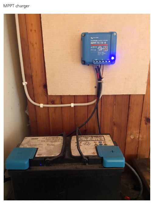
The Setup .
The setup is as follows . I plan to move the battery out of the shed as it is not best practise to have any battery system in a shed/garage/house because of the fire risk. The charger is mounted on a fire resistant material (Magnesium Board)
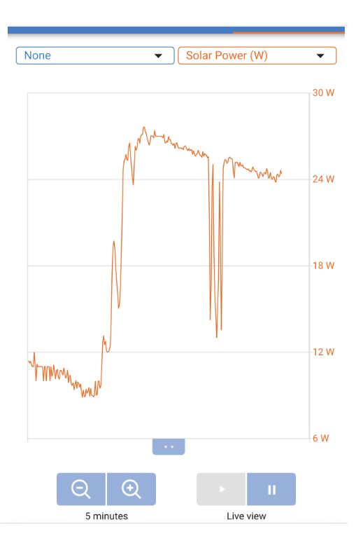
In order to access the data collected one logs on using the Bluetooth connection on your phone/tablet and the data is available. Below are different samples of the data available . The first indicates the solar power collected and the load usage. If the battery is fully charged it will take little or no power. If there is a load during the sunshine hours then the battery and solar panel will supply it.
Below is a chart showing how the MPPT charger adjusts its output/load to follow the changes in the irradiance levels (power from the sun) per second .
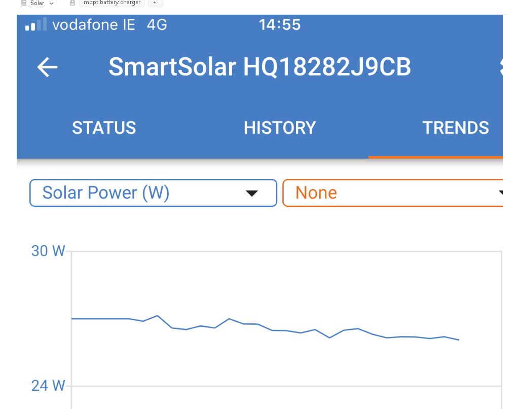
As I am able to measure the input power using a pyranometer I built I was able to see that the system was working efficiently. The data below is the output power from the charge controller when the input power from the sun was 471 watts/m2. The CIS panel provides 60 watts output when the irradiance is 1000 watts/m2 at STD (Standard Test Conditions) . This would mean that if the input power was 500 watts/m2 then the output would be 30 watts/m2. The data from the charge controller indicates an output power of approximately 27 w/m2 for the 471 watt/m2 input power.
Output power when Solar Irradiance input power is 471W/m2.
Self Build air tightness test -0.22ach with a volume of 603 m3 @ 50 pascals.
When one is building to a performance standard the day of reckoning is the airtight test. The reason for this is that when one is pumping fresh air into the house using a Heat Recovery System, rather than relying on simple multiple holes in the wall, it becomes important to control where the fresh air is coming from and where the heat is going.
Airtight Test
If air is leaking in or out around windows /doors/walls or other gaps in the building fabric then heat is lost and moisture problems in the form of mould can arise or else give rise to damage to the building fabric.
The pressure 50 pascals equates to a 20 mile per hour wind which is not too untypical in Ireland. So if one opts for the Irish building standard (a minimum standard) this equates to the air in the house changing/leaking 7 times a hour when a wind blows at 20 miles per hour. No wonder people block up the hole in the wall vents .
The current Irish building standard require 7 air changes per hour (ach) also called leakage at 50 pascals typically with no heat recovery system. As a guidance heat recovery manufactures recommend 3 Air leakages per hour to ensure that the heat recovery system can push fresh air into the house and recover heat leaving the house through its own system rather than through gaps in the building fabric.
The passive house standard for a new house requires 0.6 Air changes per hour (ach) at 50 pascals to ensure the heat recovery system works efficiently, ensure that occupants receive the correct amount of fresh air and minimise building fabric damage.
The passive house test differs from the Irish test because it must include pressurisation and depressurisation and use the volume as set out per Vn50 (EN13829).
The Test
Gavin O Shea from Greenbuild was hired for the job. He is certified/audited by the National Standards Authority of Ireland (NSAI).
The preparation for this entailed sealing all cable ducts and the inlet and outlet pipes for the Heat Recovery System. One also ensures that the shower and sink outlet traps are full of water. The overflow outlet for two water tanks were not sealed off. I did consider a duck valve but it was not in place at the time of the test.
Airtight Test
The test using the Irish method gave a result of 0.181 m3
/(hr.m2).
Gavin O Shea calculated that the equivalent size hole that equates to a result of 0.22 ach is approximately 65.25 cm2 (@50Pa) or a hole 81mm x 81mm if all of the leaks present in the dwelling were concentrated into one hole. That is about a tenth of an A4 sheet of paper.
The results of the air tight test can also help determine the selection of the Heat Recovery System. If the airtight test is lower then more options are available when selecting a unit.
From my research a passive house standard Heat Recovery Unit will cost more because it needs to be independently tested by the Passive House Institute using their test method. Heat Recovery manufactures have also the burden of putting the unit through national tests or international tests with the end result being the customer pays more. One has also the option to select a non passive house certified unit for a passive house but when calculating the performance value one needs to account for this in the PHPP software with a 12% reduction below the manufacturers performance claim.
If one wants to view certified Heat Recovery Units one can find and sort them at the following link. One can see for example at this link the capacity (Column- Air Flow Range) that these units have as it is important to select a unit that is oversized for your particular self build. I would compare it to selecting a mini car to tow a caravan up a hill compared to using a larger car. The small car will struggle from an efficiency and noise point of view while the larger car will be quieter and more efficient at the require flow rates. I will do a separate post on how I selected our Heat Recovery Unit.
I came across information over the years that may help the self builder when it comes to retrofits (doing up an existing dwelling).
This is probably the most challenging of self builds as the options are few when it comes to insulating a house that was never designed to be insulated.
The other problem for the self builder is how well were the houses built in the first place -are the construction details good?. If they are good then it may be an easy step (it is evident that today there are problems with new builds. Could it have been any different in the past?)-for example were the cavities clean, state of repair of pointing, brickwork etc., .
A Guide to doing it right
The document below is a very good guideline on renovating an old building correctly when it has solid walls.
Check for any newer versions at their web site.
I extracted a sample of the contents from the above guide by way of example.
It also needs to be realised that by adding insulation to a wall that was not designed for insulation can make the house colder if the solution is not correct, structurally damage the wall over time or cause mould on the inside that may affect your health. The above report goes through this.
Objective
The above will hopefully guide the self builder away from the problems and find the correct solution.
One needs to fully understand that one needs to choose the most robust solution that can withstand something going wrong.
Possible Products
Some of these products may be safer to use when it comes to old buildings . Some require extra measures to ensure they keep the building dry and you warm.
The hot water tank is a 300 litre stainless steel tank. Stainless steel is better at reducing stratification (minimising mixing) because it conducts less heat compared to copper. Different grades of stainless steel exist for different types of water (hard/soft). One also needs to check the type of welds used on the tank as some can not cope with certain water types.
The tank was modified to allow me to connect the solar PV water heating system (previous blog) in the future using thermosyphonic action i.e. hot water is lighter than cold water so it naturally flows from the top of the tank to the bottom (Reducing the need for pumps). The DC power from the solar panels will be connected to electric heating elements. As the solar power varies the heating elements will adjust the output power through a control unit I am developing.
Self Build Design
IfI install a solar hot water system or another method in the future this will be done with a plate heat exchanger rather than a coil. I installed extra connections on the tank for this reason. The reason for the heat exchanger is that the tank will heat from the top down. A plate heat exchanger looks like the following
Plate Heat Exchanger
If one opts for a coil it creates turbulence while heating the tank. I found it difficult to find a tank manufacturer who will install the correct surface area of a coil for a climate like Ireland. I feel most are designed for hot countries like Spain where the sun shines and stays shining. If one opts for a coil rather than a plate heat exchanger one requires a large coil surface area to ensure that most of the solar energy transferred in the least amount of time and the temperature returned to the hot water solar panel is at a minimum. In this way the hot water solar panel can operate at its maximum efficiency.
Initially when researching the options available to plumb the house I came across two main methods- Pressurised/Closed or Gravity/Open. I settled for a gravity based system because of the simplicity, DIY, reduced parts and maintainability. If one can increase the height of the gravity tank the pressure will increase at the taps.
Below is a video of what a pressurised/closed system can do (if it goes wrong and probably very rarely). When I was researching pressurised systems I felt that there seemed to be different ways of designing these and providing the necessary safety levels. I do not like systems where there are potentially hidden failures (when a safety device is supposed to work and does not).
Showers
I also was hoping to use gravity to supply the showers but it is becoming more difficult to find a good choice of shower valves and shower heads that work on low pressure . The way around this to keep things simple is to install a shower pump in a central location for two of the showers (see below). One can then use a shower head that helps control the flow rate and keep the water use to a minimum.
For one of the showers I already have a shower valve and head that works well on gravity so I will plumb this separately directly from the tank (shower 3 in the layout below).
Design
The plumbing layout for the house is shown below. (The toilets are fed from a separate gravity tank supplied by the rainwater harvesting system as shown on a previous blog.)
Gravity Fed Design
Materials
I am using Qual-Pex for the plumbing in the house. It varies in price so it is a good idea to shop around (The 1/2 inch varies from €70 to €200 for the same pipe). I ended up using 200 metres of 1/2 inch and nearly 50 metres of 3/4 inch and 25 meters of the 1 inch.
The overflow from the tank needs to be well secured or finished in copper to ensure that if the tank overheats the pipe will not sag/bend or cause a restriction.
The brass fittings are cheaper than the quick connect so I will use these. One needs a good plastic pipe cutter as using a hacksaw is not feasible. I used a Ridgid brand plastic pipe cutter and I am very happy with the quality.
With a plumbing design one needs to ensure that the size of pipes are no bigger than they need to be. One reason for this is that the volume of water in the pipe will cool down and one has to wait for this to run through fully before getting hot water at the correct temperature.
I calculated that 10 meters of 1/2 inch pipe holds approximately 1 litre of water and 10 meters of 3/4 inch holds 2.3 litres. This gives one an idea if a solution is required and the wait time.
The cold water pipes will be insulated as I am concerned that condensation could occur on the surface of the pipe.
I also tried to ensure that the number of connections/joints are kept to a minimum and I tried to place these only at accessible points.
Logistics of getting hot Water to the furthest points.
The kitchen sink hot water supply is too far from the tank so I may develop an on demand system that ensures hot water is available once certain taps are used rather flushing semi warm water down the drain and a one or two minute wait for hot water. Installing instantaneous heaters is not economical.
A way to solve this is only use one 12 volt pump and have a valve at each sink position. This pump will then feed into the gravity header tank rather than the hot water tank (I need to check the regulations) . I want to keep the plumbing connections and electrical devices to a minimum. The power to operate this can be a small solar panel charging a battery.
The plan is to develop a solution around the following -Measure the hot pipe feed temperature, Detect if the tap is going to be used and link this to controlling the pump and valve.
The only item that needs to be purchased is a 12 volt pump and a 12 volt valve and develop the control unit to suit the Irish regulations. I have started on the design of this. In the meantime I will install a third pipe in the bathroom and kitchen for the final solution.
It is now time to research the solutions available in order to guarantee a fresh air supply into the house, extraction of the stale air and recover heat before the stale air is sent on its way.
There are a number of options -Use the hole in the wall in each room (with no heat recovery), use a central extract system (with no heat recovery), use decentralised heat recovery or a fully ducted heat recovery system .
From previous experience and research the hole in the wall system does not work well taking into account that we have a wind speed of almost twice that of Germany. The system creates draughts and one has only to view the number of vents blocked up and the dependence on the correct speed of wind blowing to supply fresh air in Irish dwellings to realise it does not work.
The central extraction systems either using the stack effect (using temperature differences between the inside and outside) and Bernoulli’s principle (using wind) with no fans is an option. One can use extraction systems that are powered by fans. These do work it appears but they need careful design .
Localised vents in different rooms that use heat recovery such as the Lunos , Aereco and Glidevale iMEV system offer powered heat recovery but when I priced these they were more or less the same price as a fully ducted system and require more holes than I want through the fabric of the building.
Another system recently certified by the Passive House Institute is a heat recovery system that requires two units at either end of a building called (fresh-r). I can see the system working in an open plan environment but the cost is more or less the same as the other solutions above.
If one wants to compare certified heat recovery systems one can use the certified component list on the passive house web site Certified Heat Recovery Products. These products are independently tested by the Passive House Institute.
I will be selecting a centralised heat recovery system because I feel if it is specified, designed , installed and commissioned correctly it offers the best solution. I also plan to use it as a clothes dryer in order to get extra value out of it.
What is in a typical centralised Heat Recovery System,
It typically has two energy efficient fans, a plastic heat exchanger, filters to clean the air, enclosed in an airtight box and a means to control the fan speed. It is a simple unit but the cost is high (in line with the price of other systems above except for the hole in the wall or a stack system)
I was informed recently that the Passive House Institute charges heat recovery manufactures around €60,000 for testing and certification and then there are ongoing yearly costs that need to be passed down to the consumer. A Heat Recovery Company also needs to pay for National test (separate to the Passive House Institute) in different countries which also needs to be passed down to the consumer. There appears to be no European standard test that can satisfy all EU countries.
The product I was originally interested in was from a company called Paul but for some reason the price has risen substantially- I received a price for a Paul 450 unit two years ago and it was €2000 . It is now nearly €3000 -why?. One reason is that that the product was taken over by another HRV supplier Zehnder. I will try not select these products as I see no reason why the price of the unit increased by nearly a €1000. The price above is for large air supply volumes. A three bedroom house may only need a small unit costing 50% less.
Alternative Choices
One of the highest energy efficient certified units available is from a company called Maico-an Irish representative is available. Prices start at around €2400 for a more efficient unit than the PAUL unit . Other options are from Brink such as the Excellent 400 plus also available in Ireland. Systemair Gmbh also have units available in Ireland.
Ducts
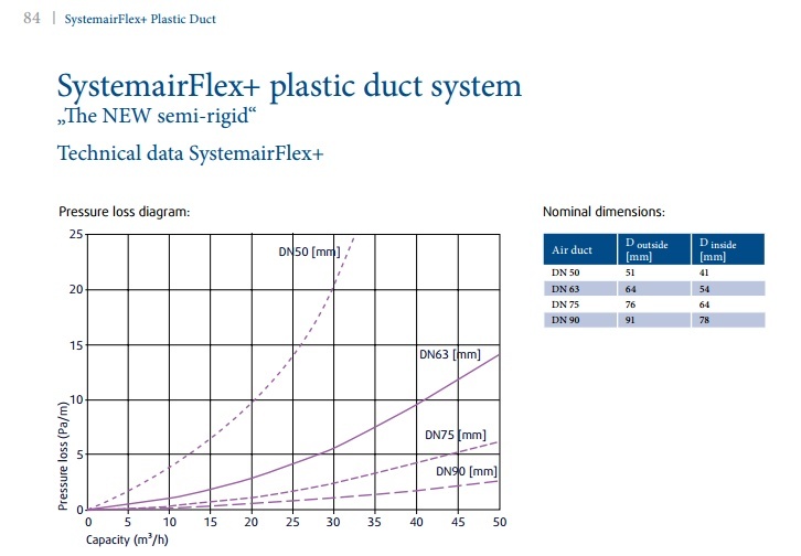
I did not think this area was going to be as complex as it is. Lets start-there are different choices of ducts from metal round, plastic round, flexible round, rectangular and all other types of shapes. The bottom line is that large round metal ducts (150-200mm) are the most efficient and quietest and have the lowest air speed.
The flexible ducts vary between two types either Aluminum or Polyethlene with general sizes between 125mm (steel), 90mm, 75mm and 65mm. The smaller the duct equates to more losses- an increase in noise and possible draughts because of the higher air speed (careful placement and selection of the outlets in rooms to minimise these effects are important). I will be trying to select and use a 90mm semi-rigid duct (outside diameter) or larger steel duct. I want to avoid the use of the 75mm duct and all its permutations such as each room being supplied with two 75mm ducts in parallel.
Larger ducts need mufflers or silencers as room noise can travel between rooms . If one has an attic or one can find a way to install the 125mm steel duct with insulation in particular routes the larger ducts may be the best way to go.
Be aware that installing a false ceiling can double the cost of the HRV. I will review all possible systems of ducts . If one uses steel I have been advised that one needs to insulate these as it can take a long time to heat up if the temperature drops leading to colder air being supplied for the initial start up.
The flexible ducts have multiple accessories to connect each part and extra cost is associated with this. The weaknesses of extra connections affects reliability. I will try and simplify the system of connections (somehow).
Ducts need to be cleaned (design and plan for this)
Keep the duct lengths short and straight to minimise losses.
Use large radius bends rather than 90 degree bends.
Consider placing ducts in the foundation when building new.
Some plastic ducts are antistatic (minimises dust collection on inside)
Some plastic ducts have antibacterial liners
Some plastic ducts are odourless and use physiologically and toxicologically safe polyethylene.
Some plastic ducts are smoother on the inside than others (minimises losses and reduces noise).
The non monetary factors for using a centralised Heat Recovery System that I can think of are:
■ comfort (help to filter diesel particles , pollen, outside smog etc from the forced incoming air)
■ building protection and health/hygiene (remove high level of moisture from cooking, showers, baths, and people that could damage the fabric of the building, CO2 from persons in the house and VOC (chemicals from furniture, beds, floor carpets, paints, plastics etc) and supply enough oxygen to get a good nights sleep. Reduced noise because windows do not need to be left open and no holes exist in the outer walls of bedrooms.
■ security (can keep windows closed)
■ thermal energy efficiency (recover up to 90% of the heat energy leaving the building)
The Plan
I want to see if I can design the HRV with the 150/125mm steel ducts or use the 90mm polyethylene outside diameter ducts with the antibacterial liner, antistatic liner and low emission polyethylene.
Each of the polyethylene ducts return to either a supply manifold or extract manifold (see example below).
HRV Manifold
If I end up selecting the 150/125mm steel ducts these will use no manifold and the individual rooms are tapped into the main duct.
Extra Functionality Planned For the HRV
In order to get the most value from the centralised Heat Recovery Unit I plan to make a special cabinet to dry clothes using a feed and return air supply. I will add a heater to the cabinet to give the clothes a drying boost where necessary.
Calculators
An interesting calculator I found is one that calculates the losses of ductwork and air speed. One can experiment using rectangular versus round ductwork and the inner roughness of the ductwork here. One can see the air speed change as one reduces the size of the ducts. There are another few options on the right hand side menu to calculate other factors.
Example of Duct Losses
Flexi Duct
Background Research and Notes
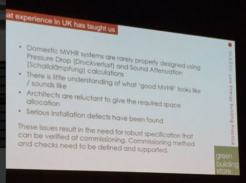
MVHR are not a fit-and-forget systems
Based on European CEN Standard 13779 ventilation for ‘medium’ air quality should be at least 10 L/s per occupant (15 L/s for high indoor air quality).-non residential
Ventilation rate of 8 l/s (30m3/h approximately) per person identified in CIBSE Guide A8
In order to achieve an air exchange of about 0.33 ach (air change per hour), one would have to open the windows wide for 5 to 10 minutes every three hours – even at night! –Source
Biggest complaints -noise and draughts (over dining area, bedroom areas etc) causing users to switch the HRV off.
Balance the air going in against going out-not practical to reach 0%. Aim for less than 10%-allowable imbalance between intake and exhaust air flow for these systems is 10%
Filters not changed can increase (double) the cost to run because the fans use more electric power to send air around.
Ensure that the HRV is accessible in order to change the filters.
A good strategy for the summer appears to be to reduce HRV speed/flow rate and open windows.
Total cost of HRV if left on appears to be around €60 for electricity and €60 for filters (Once a year). Check cost of replacement filters for own unit.
Ducts need to be cleaned every few years so the design needs to make it accessible.
A larger HRV unit than required can be more silent because it does not have to work near its full ventilation capacity.
A measured air noise level of less than< 24db for bedrooms (Finnish Guideline) . Can it be specified and delivered?
Noise levels up to 30 dB(A) were described as “too noisy” by more than 40 % of respondents. The standard for certified PassivHaus dwellings [13] is a limit of 25 dB(A) in both living rooms and bedrooms. Source
Maintaining indoor humidity below 7g/kg should help to reduce the risk of excess mite growth.
Note that air speeds greater than about 0.3 m·s–1 are probably unacceptable except in naturally ventilated buildings in summer when higher air speeds may be desirable for their cooling effect.CIBSE Guide A8
Significant problems were found with the commissioning of HRV systems, with only 16% of systems being found to have been commissioned correctly with respect to air flow and balancing. Source
44% of kitchens meeting the minimum requirement of 13 litres per second.Source
Measured air flow in 88% of systems utilising rigid ducting were equal to or greater than their design air flow values, whereas between only 40 and 44% of systems utilising flexible ducting met their respective design value. Source
Any leakage through the dwelling envelope will have an impact on the efficiency of the heat recovery component. Source
Lack of appropriate airtightness, lack of complete commissioning, poor air flow and extract rates (and associated lack of compliance with regulatory standards), lack of balance and inappropriate duct types. Source
Wolfgang Feist@WolfgangFeist-You don’t believe this?The “trick” is:We have a F8 fine filter at the external air (“fresh air”) inlet, therefore supply air is very clean
In another technical paper the following was noted as the cause of excessive noise. The source of the document is here
Extract from document shown below
“The following list of issues are all taken from actual findings on investigations that have been reported. Issues that can lead to excessive noise for occupants are noted under the following headings of design, installation, commissioning and maintenance.
Design issues
• Centralised MEV or MVHR unit located in inappropriate place for break out or structure borne noise, e.g. bedroom cupboard or on rafters in loft above a bedroom.
• Poor ductwork layout – too many bends can lead to additional fan pressure requirement and regenerated noise
• Specification of flexible ductwork
• Inadequate attenuation of duct borne noise
• Installation issues
• Ductwork kinked or damaged inhibiting flow
• Ducts not connected up to supply or extract valves (which will inhibit flow and require higher fan setting)
• Wrong type of outlet fitted (using extract outlets for supply air can lead to regenerated noise)
• No anti-vibration mounts used
• Failure to ensure ductwork is clean when installed prior to commissioning
• Use of flexible ductwork where not specified”
Recent Research
I note the above is summarised at the recent passive house conference (see below).