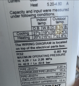
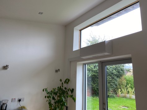
Background– As previously discussed we had used two storage heaters to heat the house. The capital cost of this heating system wa €70. The passive house standard requires a heating load of approximately 1 Kwh for every 100m2 on the coldest day of the year. With the increase in energy prices and the slow pace of global warming the off peak electricity costs have risen from below 9 cents to its current price of 19 cents. We then made the decission to install an air to air heat pump as shown below that would reduce the real cost to approximately 1/3 rd of what we use to heat the house. The unit cost approximately €700 to buy and approximately €1000 to install.
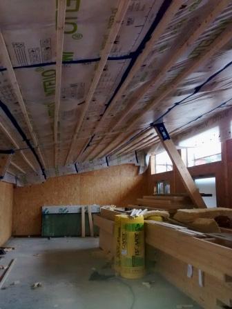
In this blog I will discuss the learnings from the use of one air to air heat pump to heat a 200m2 house designed with the PHPP software to the passive house standard. The location to install the internal and external unit is very important. What is not covered in the passive house standard I feel is the dampness in Ireland that penetrates the human body to the bone. The operating design temperature of the passive house is generaly 21 degrees celcius. We found we needed 22 degrees for the living room and 18 degrees approximtely for bedrooms. The kitchen/dining room temperature will be explained below.
How to deal with the Irish Weather

The other factor when one installs a central heating appliance whether it is a stove, an air to air heat pump or an electric fire in a passive house is I feel is to ensure more heat is available in one particular room to thaw out. This I feel is a good thing for the Irish climate because we found the constant temperature of 21 degrees one was slow to heat up when we came in from the cold. I feel one needs a stronger heat source to drive that initial dampness out of ones bones. We can all relate to standing in front of a fire to thaw oneself out, this can take the form of standing in front of a fire, a stove or an aditional heater. In our case we used the air to air heat pump by installing it in a selected room.
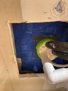
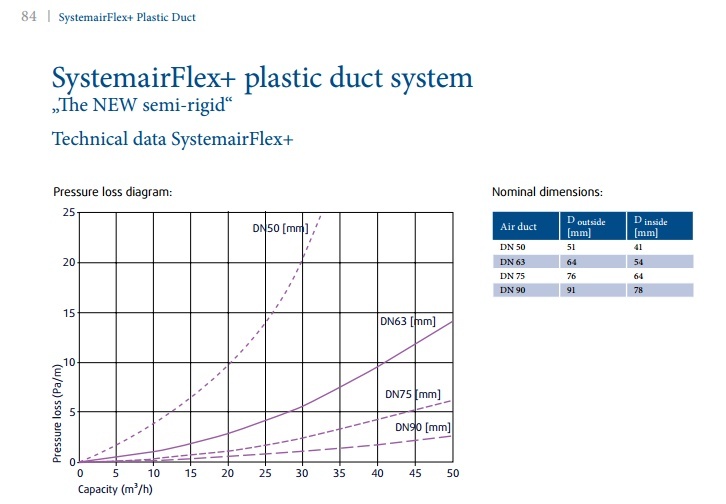
The location is important because the air to air heat pump does blow out warm air and this would be uncomfortable if it was installed in front of a seating area. Our selected location was the kitchen /dining room and aimed between two worktop islands in the kitchen that normally only has foot fall. In the dining room/kitchen I also installed two seperate air supply ducts (92mm each) with one extract duct. This also benefits in ditributing the heat throughout the house as more air is supplied into the kitchem/dining room rather than extracted. Most of the extract air ducts belonging to the Heat Recovery Ventilation (HRV) unit are also at the far end of corridors of each living space which means that air has to be drawn from the supply areas to the extract areas for ventilation.
The first room we go to if we encounter that outside cold damp Irish weather is the kitchen/dining room where the air to air heat pump is installed. The temperature in this room is around 24 degrees which is then dispersed to the rest of the house by the means outlined above. As it is a single storey house the heat does move around slowly with the help of the heat recovery unit. If it was a two storey dwelling with a better form factor then I would imagine the heat would rise to the bedroom areas easier if one wanted higher temperatures than what we use.
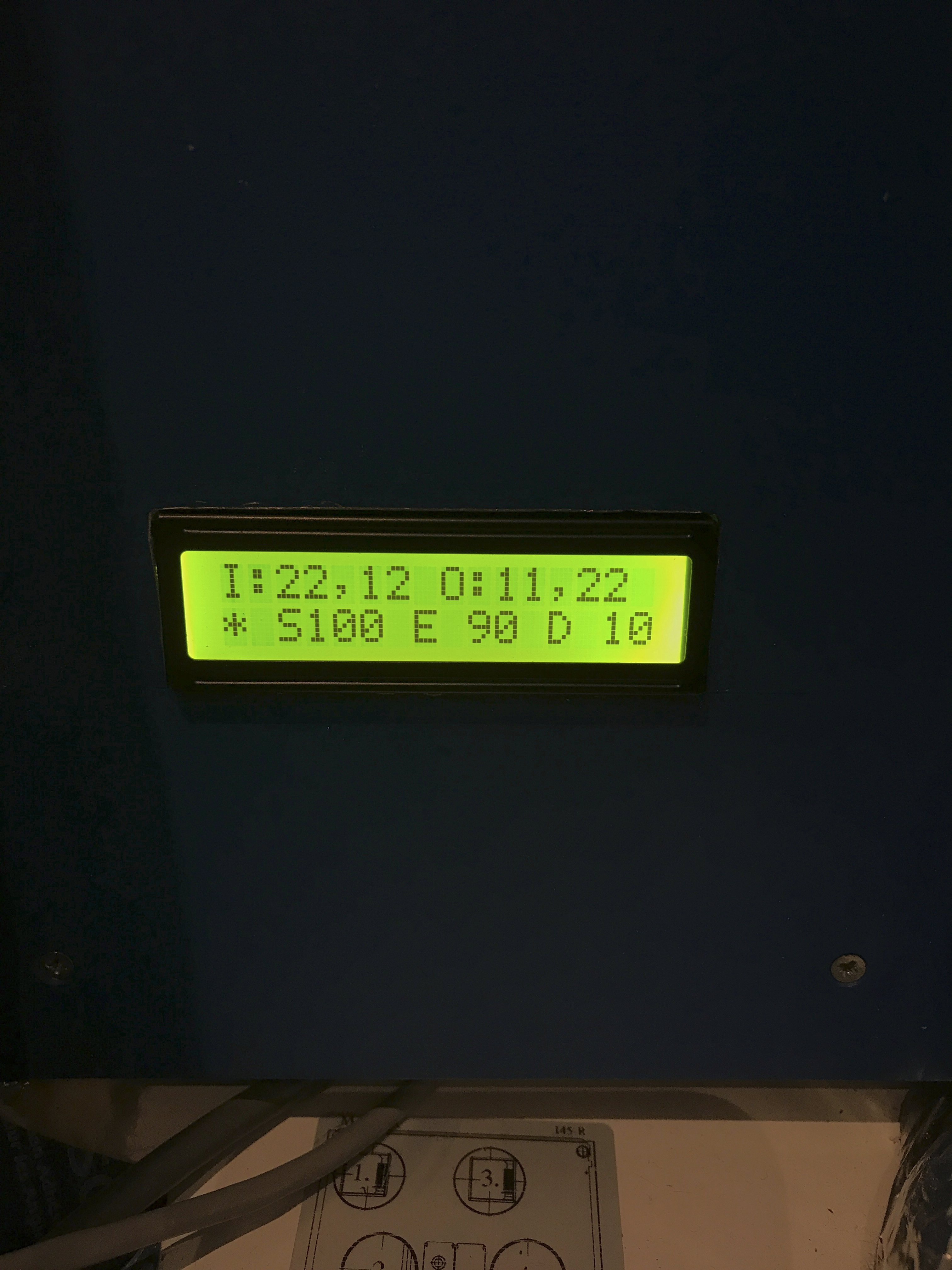
I also experimented with the extract and intake fan speed rates of the HRV as this affects the temperature of the house. If one increases the HRV ventilation rate higher than one needs for a healty air supply then more energy is used by the heat pump to keep the temperature at the levels required.
The other factor to take into account is that we found that if more doors are closed then the distribution of heat can be controlled in the house. For example when measuring the co2 rates at night in our bedrooms we found that we needed a higher air flow when more doors are closed around the house. What we found works is that if we reduce the HRV fan speed during the day (which reduces the heating load of the air to air heat pump) when people are using more of the house and increase the HRV at night because more doors are closed this works. So simply by closing and opening doors one can control the temperature of the house -for example if we leave the TV room door open during the day the heat enters that room. If one closes the door then the temperature drops to 1 to 2 degrees less than the rest of the house.
We also recently installed a simple electric hop extraction unit with a carbon filter that is not ducted to the outside to reduce cooking smells around the house because more air is supplied to the kitchen/dining room than extracted .
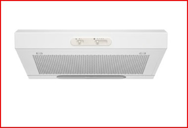
I think one also needs to have an extraction unit for air fryers as this is now more widley used than the hob to reduce the cooking smells being dispersed around the house. This will be a seperate project to be accommodated for when we install a new kitchen .
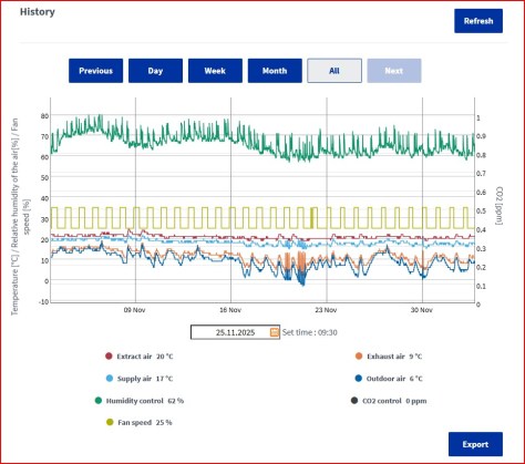
The performace for the Samsung 1.6 KW air to air heat pump over the month of November 2025 is as follows .
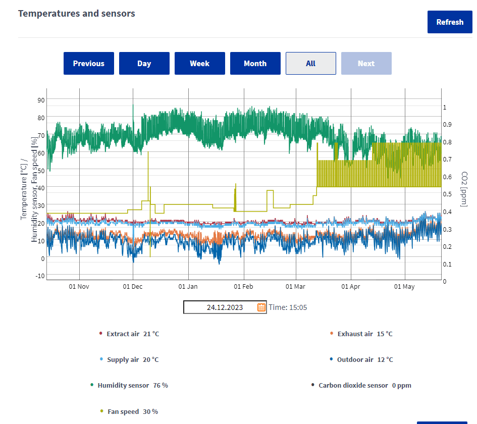
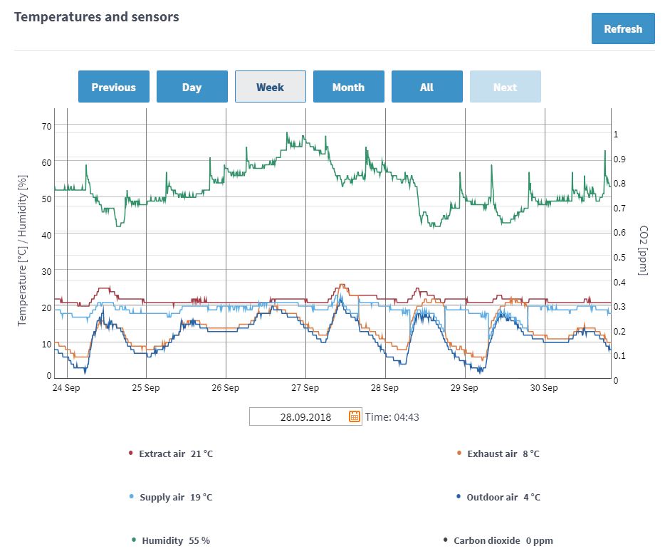
The electricity usage from the 3/11 to the 3/12 2025 was €1.60 a day when one takes into account the current night rate and day rate of 19 cents and 29 cents. The lowest outdoor temperature recorded was -1 degrees celcius . The total power consumption was 184.11 KWh which equates to approximately 6 kwh per day to heat the house to the slightly higher temperature of 22 degrees in the main living area and the dining/kitchen room to 24 degrees 24 hours a day . Below is the plot of the air temperature recorded by the Airflow Adroit DV145 HRV unit I installed . The bedroom temperatures were approximately 18 to 19 degrees celcius.
HRV Data November to December 2025
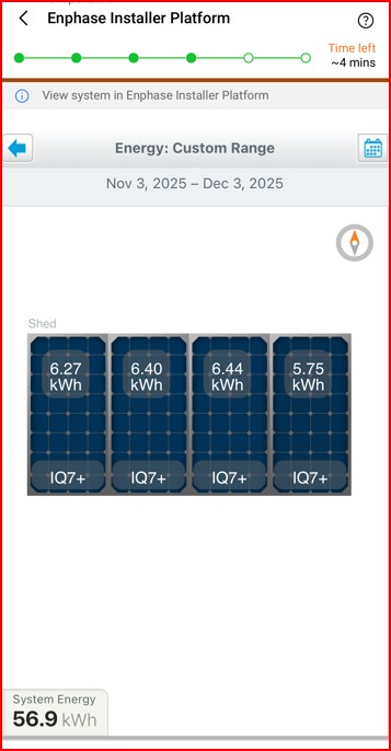
SOLAR PV electricity offset
I have installed 3kw of solar PV panels and plan to add another two panels in the comming weeks. Solar PV panels can now be purchased for approximately €60 each (450watt). As I use the enphase micro invertor system the installation is easy to expand as discussed in another blog. The only disadvantage in our house is orientation as most of the solar panels are pointing north at 12 degrees while in order to maximise the solar gain of winter sun one needs 60 degrees panel orientation in a south-east direction. Even so for the month of November above 56.9 KWh of electricity was generated. If I was to offset the electricity generated the cost of heating the house would drop to around €1.02 per day when using the day time electricity rate of 29 cents per kwh.

CO2
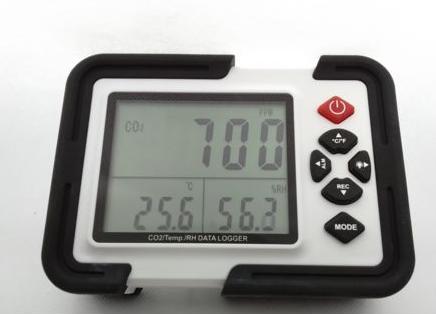
I started recording the co2 readings this month in the hallway rather than in one particulat room. A new co2 unit has been ordered so that I can get seperate reading for different rooms. The co2 readings varied from 672ppm to 1000 ppm in the hallway as the house is open plan with no doors in the kitchen/dining , the living room or onto the hallway.
Air to Air heat pump
For all the above measurements I set the heat pump to 75% capacity and a fan rate of 2 (4 available to adjust the air flow speed) which equates to 50% . My undertanding is that if one can set the heat pumpl rating to a lower output capacity this extends the life of the heat pump. Currently the temperature setting on the heat pump is set to 23 degrees in the kitchen/dining room.
Air to water cylinder-The next plan is to install in the kithen/dining room a small air to water cylinder to reduce the cost of heating water. Some of these units have a seperate coil where one can connect solar hot water panels with drainback or vacuum tubes to get free water heating in the summer months. We currently heat the water on a night time electricity rate of 19 cents. While this electric element is a simple low cost method and easy to maintain with the lowest installation cost -the long term cost of electricity is only going up. The plan is to reduce this rate to a third of the price with a unit like that shown below.

To be Continued