Other advantages of an Air to Air heat pump compared to air to water heat pumps is the ability to supply heating when it is required and quickly switch off the unit if there is solar gain in the winter (the sun has been known to shine in Ireland in the winter months). The air to water heat pump will have a slower response time through the concrete floor.
Installation-The installation of the internal and external unit needs careful design/planning. Both need to be considered at the same time. The factors to consider for the external (Inverter) unit is a location that is not subjected to high winds (higher winds will mean lower temperatures during the heating season and reduced efficiency), mounting the external unit at least 100mm (I used 300mm) from the rear wall (restricting air increases the energy usage). There should be no air flow restrictions in front of the unit either. Mount the unit on a secure and flat surface (the external inverter requires a flat surface so that compressors are balanced to reduce vibration). Vibration leads to lower reliability. The length of the pipework also needs to be considered and noise levels. The maximum noise level for our unit is 61db if on full power.
The external unit requires an electrical isolation switch and a condensation drain for the cooling season (it removes moisture from inside the house).


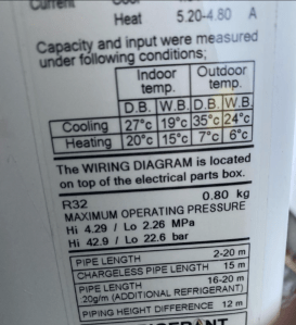
Power Consumption-The maximum power consumption of the external unit is 1.6kw with a typical power consumption of 1.08kw to produce up to 4kw of internal heating. Typically a passive house requires 1kw of internal heating for each 100m2 on the coldest day of the year . Our home is 200m2 so 2kw is required. The 4kw output power will allow more heat capacity if required. Most Air to Air heat pumps have an option to control the output power using the remote control. One can reduce the power to 50% or 75% of its rating. I will set ours to 50% for year 2 (2024-2025) which approximately equates to a max heat output of 2Kw on the coldest day of the year. This has the advantage for passive house builds of increasing the life of the Heat Pump compressor and ensuring the unit does not use more power than is required. It will also reduce the noise level by 4db (which equates to a reduction of noise by approximately half).
Typical Operation-The operating temperature range of the external inverter is –15 degrees to +24 degrees in the heating cycle. The typical internal heating temperatures achieved for 6 degrees and 7 degrees outside temperatures are shown below. Most heat pumps will also have an automatic defrost cycle when the external unit freezes over due to low outside temperatures. No heat will be delivered inside the home during this cycle and it only lasts a short period of time. If a house is designed with the passive house software (PHPP software) it could take a day or two for the temperature to drop significantly due to the highest air tightness standard in the world (0.6 ACH), quality control around the building fabric and designed to a performance standard.
It is also important to mount the unit above ground level so that snow does not block the unit from functioning. A HO7RN-F (A rubber/Neoprene flexible cable) 4 core cable is required to connect the outside unit to the isolation switch (red switch shown below) which in turn requires another isolation switch inside that in turn controls both the inside and outside unit.

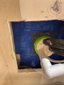
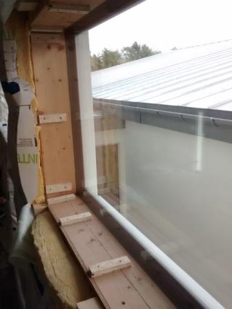
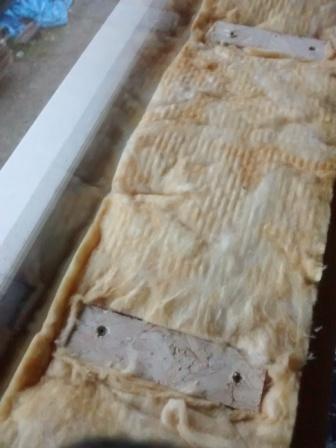
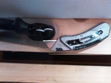
Cables and Ductwork-The cables and ductwork installation for a heat pump with a timber frame construction requires care during installation. When locating the cable and duct route through the wall use a narrow hollow pipe to find a path through the insulation and then drill through this pipe. If one uses a drill on its own with fibreglass insulation will wrap itself around the drill and leave thermal gaps in the wall and result in thermal bridges. The method I used is shown below. I used a rubber airtight gland to seal the larger duct. Ensure that this hole is mechanically sealed during the interim works from any rodents entering your build.

Power Usage-For year one of the installation I experimented with different settings -example using a high heating mode during off peak lower cost electricity and then returned to lower heat output during day. For year two I will set the unit at 50% of its output heating capacity and try an option called ECO mode which automatically reduces the temperature over time. For the last two weeks in this mode (October week 1 and 2) the unit used 20Kwh (€5 @ 0.25 cents per Kwh) to heat the house. The input power used by the air to air heat pump was approximately 300 watts when heat was required. The plan is to increase the number of solar PV panels to offset this 300 watts during daytime use. The power consumption varies as the external temperature changes. In the first year we used between 28Kwh per week up to a max of 50kwh during the first year of experimentation during the winter heating season. A power meter is now installed to record the daily/weekly and monthly power usage as shown below.

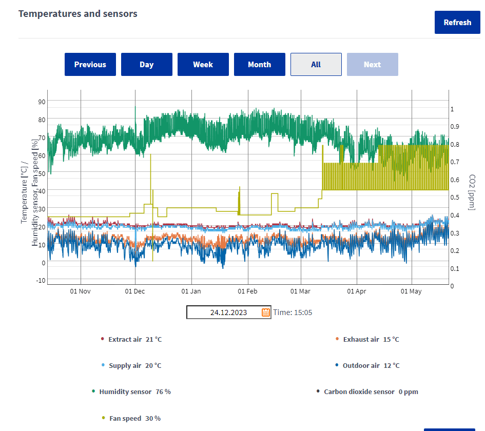
Below is the HRV (Heat Recovery Unit) temperature /humidity plot over the 2022-2023 winter period with the air to air heat pump. I reduced the HRV fan speed to minimise the amount of energy consumed in the winter time and increased it at the end of the winter season as shown below .

Internal Unit-The internal unit requires a height above floor level of 2.4 meters and at least 65mm clearance above the unit. In our installation there is approximately 1000mm clearance above the unit to allow the unit to blow air upwards to ensure a more balanced room temperature and air flow in the room. This is a built in function of this particular unit .
Further Experiments and Research-I am also experimenting with a secondary heat distribution unit to improve heat flow around the living area of the house in year 2 in order to optimise the temperature differences one finds at ceiling height versus floor temperature.


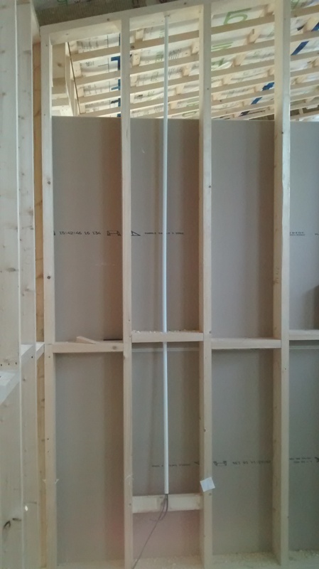


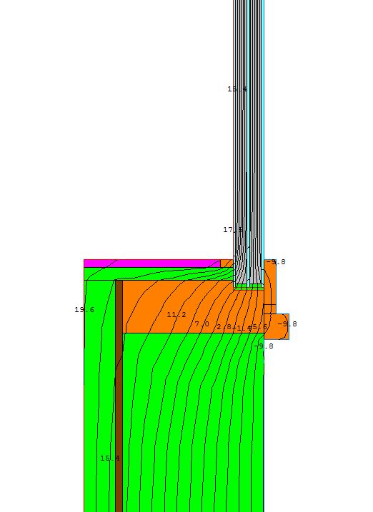


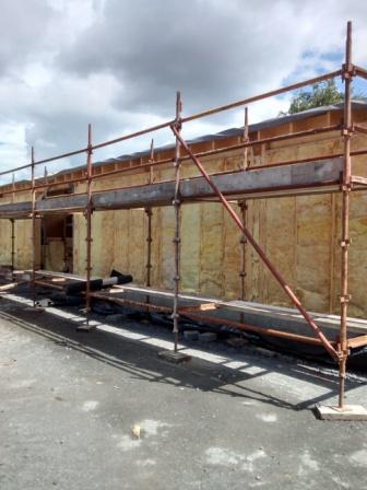
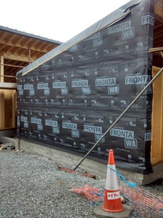
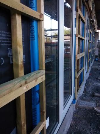

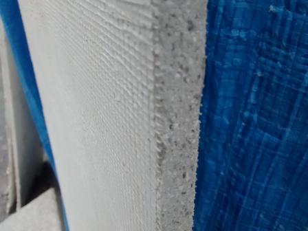

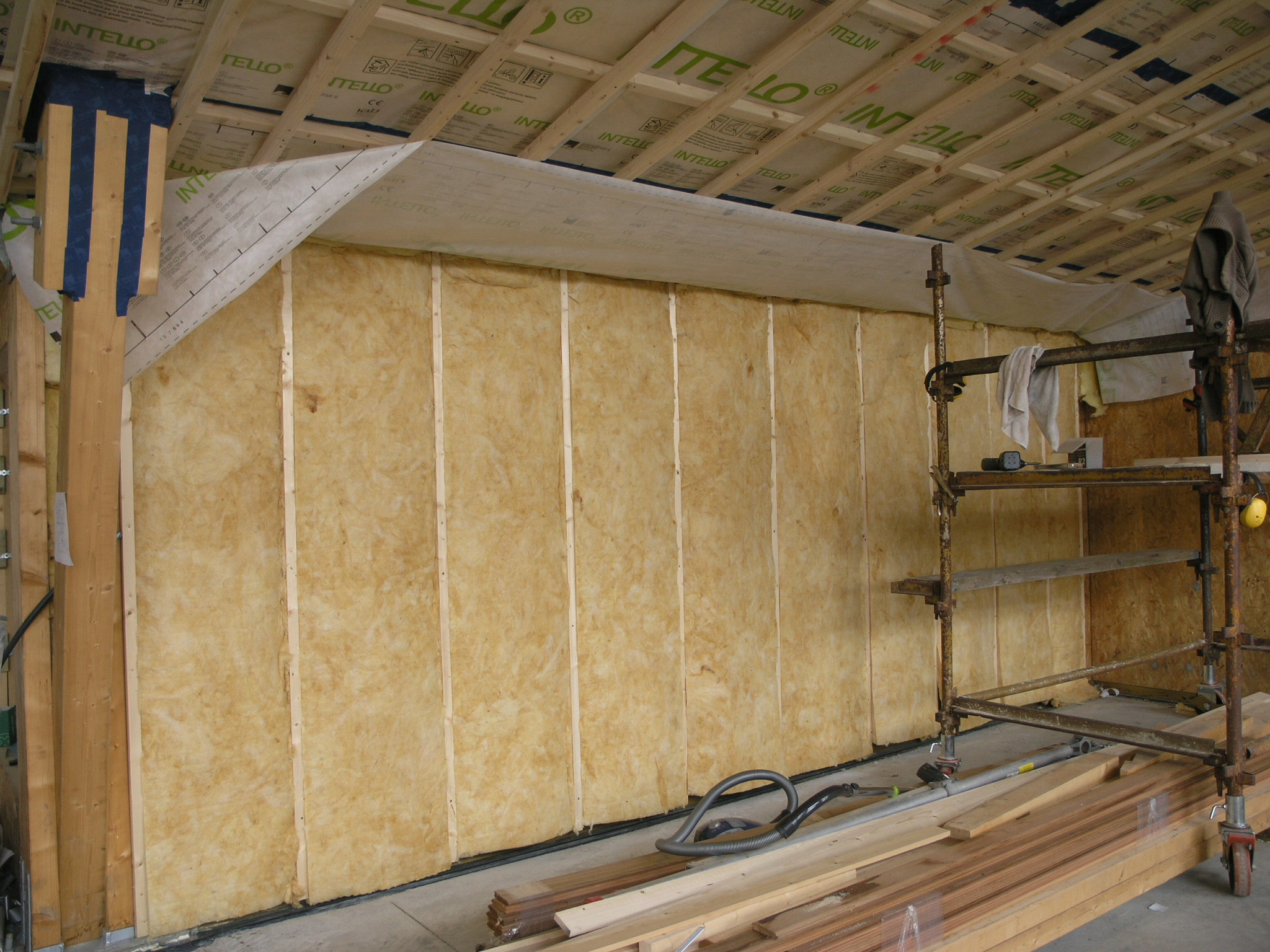
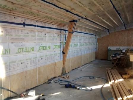
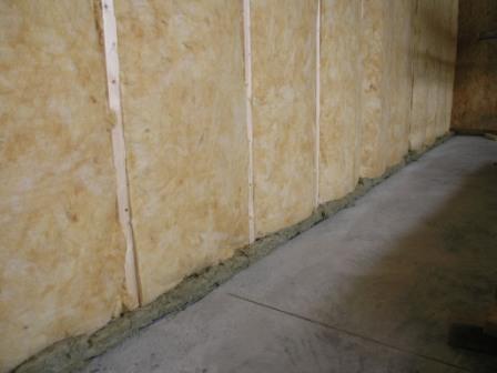
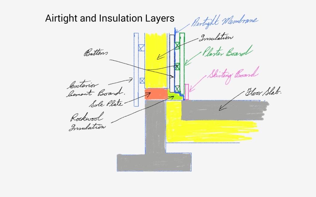 Wall Layers with Insulation