I am just getting around to installing the light switches . This is how the finished light switches look at the moment. Later on I plan to change the front plate of this switch to one of the other options such as glass, wood or marble.
This is what the above light switch looked like before installation. Standard switches can be used if one uses the method described below. I used a screened alarm cable to connect the KNX binary device known as a universal interface. This voltage is extra low around 3 volts DC.
KNX Distribution Board
As seen above this is what a typical KNX lighting distribution board looks like. One has a Power Supply (top left) and a programming Interface (next to power supply) . The three actuators (12 way) on separate rows send power directly to the rooms or other devices such as towel heaters. Functionality such as timers, last state before power failure, purging (automatically switching on pumps/valves to ensure they do not stall) etc is already built into the KNX technology.
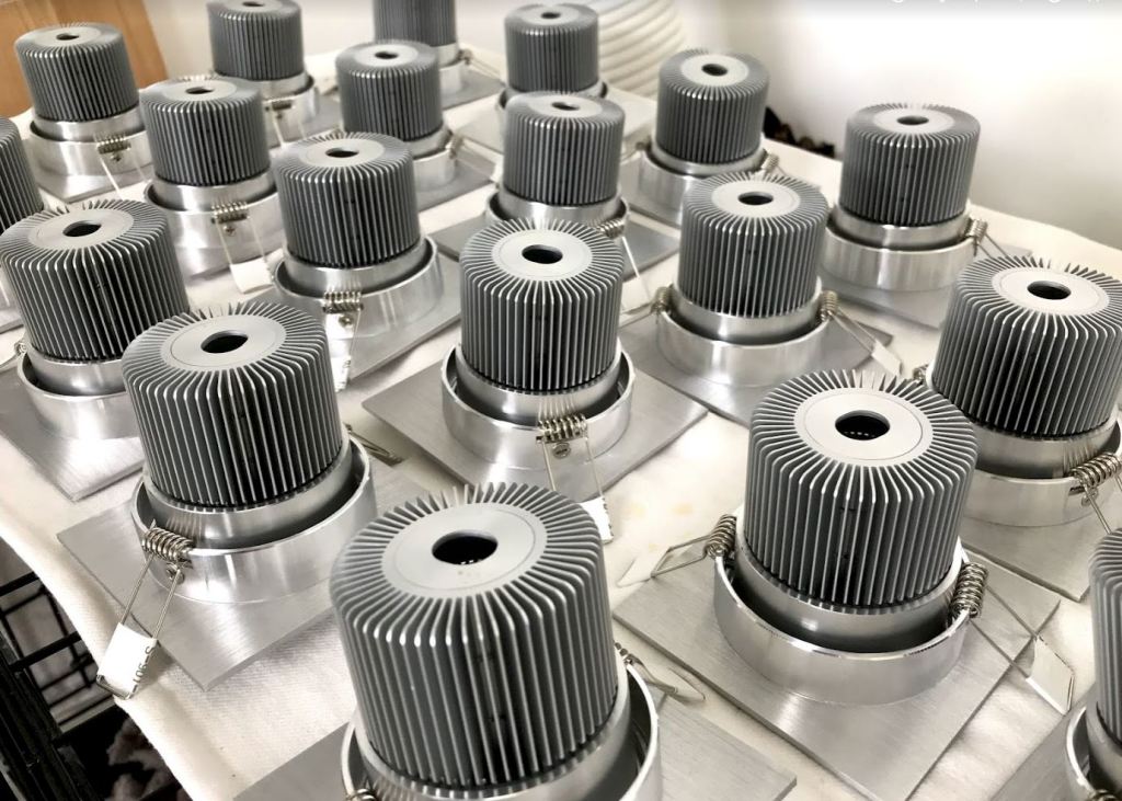
LED Housings before I assembled the LED and its LED Driver.
Led mounted on Heatsink
This is one type of LED Driver I have used to power each LED. Typically when one buys an LED they have already tried to fit all the electronics contained in the above unit in the lamp one buys . This is one reason why led lamps do not always live up to their expected life time of 50,000 hours. The majority of LED failures are due to heat stress. I am using 9 watt LED in the housings shown above and the Power supply is a separate unit. For lower power LEDs one requires less electronics.
Floor laying continues with the Junckers System. The floor boards are 22 mm solid wood with a proprietary clip system. Each of the metal clips (shown below) connect each floor board. The clip type one selects depends on the expected humidity levels in the home. I used a soundproof underlay on the concrete floor. One can also nail this type of flooring.
Skirting Board Lighting
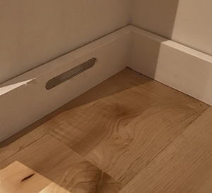
I started the design of the skirting board lighting that will be powered from a DC source (battery) connected to a solar panel. The idea is that this lighting would be on when it is dark and would also act as a lighting system if there was a power failure in order to minimise the use of candles.
The light output of this lighting would be equivalent to a candle and they are placed in bathrooms and corridors in order to allow one to walk around the house at night without switching on the main lights.
A first fix of how they will look is as shown below.
In a previous blog I discussed the advantage of using KNX for the lighting control only. Some of the KNX control options are expensive so in order to keep things simple and affordable I have decided to use the following devices to control the lighting. As most of the LED lights are using around 5 Watts of power I will also eliminate the dimming functions and ensure that the layout of the lights in the ceiling can be switched on separate circuits in the larger rooms (a simple form of dimming in a way).
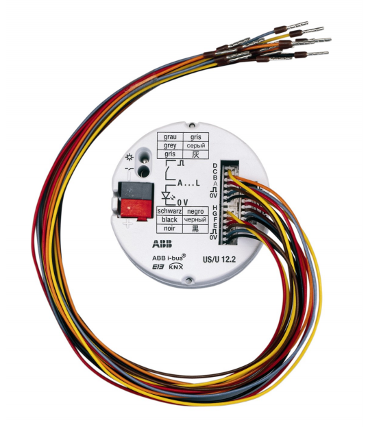
Universal Interface
The hardware required will be a KNX binary input /output device with 12 inputs/outputs to connect to standard light switches. The advantage is that the cost is reduced by not using a special KNX light switch. A single KNX switch can cost up to €100 while a simple mechanical switch that costs €2 or €4 approximately can carry out most of the primary switching functions and is designed to work on the KNX system.
My preference and research on the best value for money is a product made by ABB called an Universal Interface US/U 12.2 . Expect to pay around €120 for one of these which has 12 inputs/outputs (Equates to €12 euro per room). It can also carry out dimming control with a suitable KNX actuator (device that switches the power from a central distribution location). There are numerous other functions built in that are relevant to lighting and indication control.
EIN KNX Interface
The plan is to mount one of these Universal Interfaces in 4 different areas in the house (The size of one of these units is approximately 52mm in diameter) . A maximum of 12 light switches will connect to this Universal Interface. It is recommended to keep the cable feeding the light switches to a maximum length of 10 meters (although I have found it works reliably up to 100 meters). I will be using screened alarm cable (6 core) to each of the switches. In this way I plan to leave a spare core for each switch so that other functions can be applied in the future without re-decorating. I will be using a push to make light switch as this allows one to use the same pair of cables for two way control and optimise the use of the cores in the cable.
Each 12 channel Universal Interface will have its own KNX 12 channel switch actuator ( see below-it can control 12 different lights using 230 volt power in the building) that will switch the LED lights. One location to source these is http://www.eibmarkt.com
Switch Actuator
For the switch actuator (relay control of the lights) one can select the equivalent 12 channel KNX actuator. If one goes to the above web site or other KNX web sites and enters EIB KNX switch actuator 12-fold, SA.12.16in the search engine one will find these units. Expect to pay around €230 for one. If one goes to http://www.eibmarket.com they have one for around €239 including VAT. This works out at a cost of around €20 per room along with the savings in wiring and flexibility in the future as discussed in the previous blog.
Dimming Option
If one wants to dim LED lights one needs to research a suitable dimmer for the LED light. There are different technologies used to dim LED lights so one needs to establish which LED lights to use first before committing to purchasing a dimming function. I am aware of two types such as leading edge and trailing edge controls for dimming. As I will not be dimming the low wattage lights a simple actuator is all that is required.
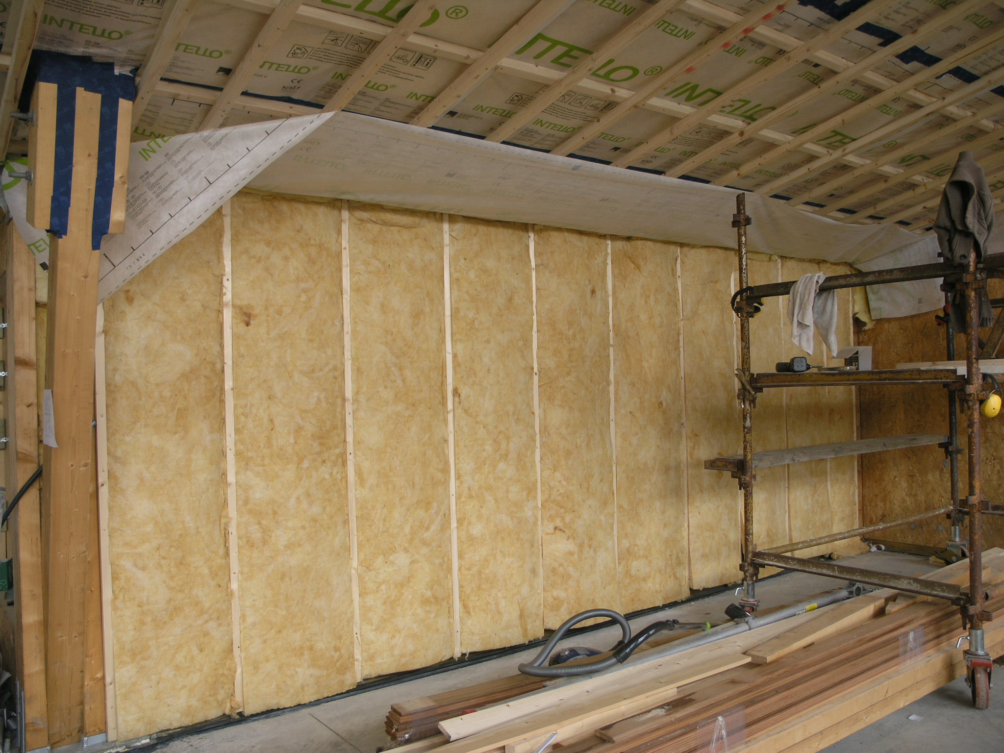
For the internal wall build up I am using a double batten wall system. This wall system allows one to easily install services. In a previous experiment on building a workshop (used as a means to experiment on a small building before commencing the house) I installed a single row of horizontal battens on the OSB board. This made it very difficult to run services that need to run vertically. I had to install metal protecting plates and cut notches in the wood in order to ensure that I did not damage wiring due to the final layer of plasterboard screw fixing.
When one uses a counter batten system it facilitates running services such as power, lighting, phone, internet, alarm etc without the risk of screw damage. This system also helps to reduce the cost of installing these services (see the image of a cable behind the batten below).
One can make use of a wall system like this if a soft insulation such as cellulose or fiberglass is behind the final batten which will support the plasterboard finish.
A row of battens run vertically behind the membrane in order to facilitate running services.
When working at ceiling level one may need to use a counter batten system in order to allow for recessed lighting otherwise it will mean installing special electrical enclosures cut into the airtight membrane. I have installed counter battens to a depth of approximately 90mm in the living and kitchen areas for LED downlights (see the previous post link on the 26/04/2015). In the bedroom areas I will only use a single batten system in order to install hanging pendent fittings.
Floor Level Insulation.
At floor level I installed Rockwool insulation for two reasons -one was to minimise the thermal bridging (heat loss around the wooden sole plate that the timber wall sits on) and the second reason was to minimise the damage to the insulation if there was a water leak.
I carried out a test where I placed 50mm of Rockwool RWA45 (product in the left bowl) and Metac (fiberglass-product in the right bowl below) in water in order to see what would happen if there was a leak. The Rockwool absorbs very little water but the fiberglass sank and became completely saturated and would possibly never dry out. Both insulation’s were submerged initially and then left for the duration of the test.
Rockwool versus Fibreglass for water damage.
Below is an image of the Rockwool installed at floor level under the fibreglass in order to minimise the risk of insulation damage at floor level and minimise thermal bridging.
Rockwool Installed at Floor Level (green colour)
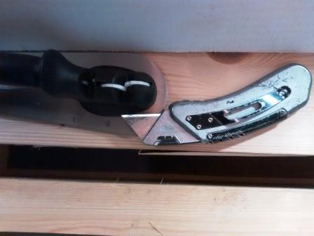
Airtight Membrane Installation
When installing the airtight membrane I was surprised how quickly the knife goes blunt. Rather than using the disposable knives and blades I now use a sharpener with the knife.
The plan is to install led lighting. I will also install low level background lighting that operates on a 12 volt DC supply. The idea is to have this low level lighting operating from dusk to dawn and act as a backup to power failures and hopefully reduce power usage by not having to switch on/off the main lights as one goes around the house at night. The light level planned will be equivalent to the light output of a candle and these will be placed approximately 2 metres apart in hallways and bathrooms near the floor level.
For the principle lighting I will be using Sharp Zenigata Leds that have a very high Colour Rendering Index value (CRI). The CRI is an important factor in trying to reproduce the colours of everyday items. One may have noticed that the majority of led lights reproduce colours poorly ie. red does not look like red, green does not look like green etc.
The CRI value is one of the standards used to compare the colours reproduced by Led lights to that of a halogen/incandescent bulb. Most manufactures may only indicate a colour temperature figure like 2800 degrees kelvin. This works independently of the CRI value. No LED manufacturer has of yet been able to reproduce the colours an incandescent bulb or halogen bulb can reproduce.
Below is the best explanation of CRI values I came across.
Sharp CRI Explanation Graph (The orange line above is a typical led and the green line is the sharp led and how it reproduces different colours)
Reliability
A factor that determines the reliability (life) of LED lights is the management of heat and the ability of the manufacturer to try and squeeze lots of electronics into a lamp that operates at around 60-100 degrees Celsius (high power type that can replace 50 watt halogen lamps). Thetwo factors do not work together so I plan to separate the electronics from the heat by only installing the LED lamp in the ceiling fitting and use a separate device called an led current driver to power up to 3 led ceiling lights. In this way I hope to get the full 10-15 year life of the led lamp. (I will probably want to change them before that time though as the technology advances).
Self Build Housing for the Led lights.
I could not find a Led lamp that used the sharp petite zenigata high CRI led and be sure it was designed properly. For this reason I decided to build my own. In order to do this one needs a suitable heatsink (a device to remove heat efficiently) and enclosure for mounting the led light in the ceiling. A heatsink will usually have a power rating that specifies what size led it is suitable for.
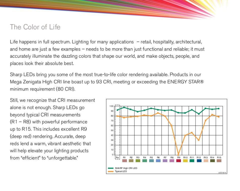
Below is a 6 watt heat sink. This is approximately the size heatsink that is required to replace a 50 watt halogen down light. One can see the challenge manufactures face in trying to adapt led lights to fit into existing halogen lamp housings with all the electronics and a suitable heatsink that would extend the life of an led.
Heat Sink typical for a 5 watt Led
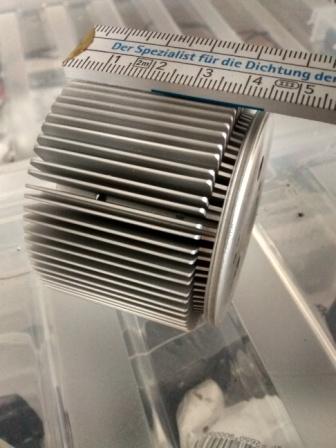
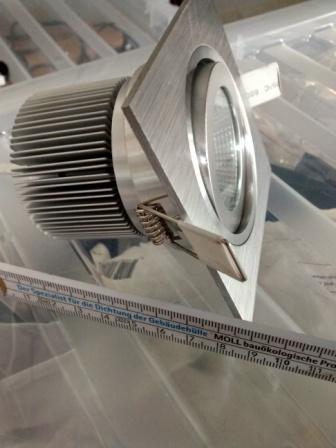
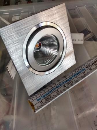
The principle as stated before for this self build design is that it allows me to remove all the electronics to control an led into a separate enclosure that would not be effected by the heat. By doing this reliability is increased. In other words simplify the design by lowering the component count and thus extend the life. The pictures below are the finished Led Housing .


