Wall Finishing and Fire Compartmentalisation
Sanding
The golden rule is-avoid sanding as much as possible by ensuring that the knife finish is smooth at the edges and as close to a final finish as possible. If one had to do this manually with a sanding block and pole it would be a tough job.
Thankfully over the years people have been improving the tools. I was lucky enough that the builder loaned me his sanding machine. I just needed a hoover to manage the dust which was picked up free on the free cycle web site. The sanding machine looks like the following:

Even though the above Flex machine makes the job easier and faster it still is a physical job especially when working overhead. The hoover was not designed for the above but it worked out OK once the bag and filters were cleaned regularly.
I would suggest safety glasses when working overhead and a face mask at all times.
Technique for Sanding Used
The joints had a second coat of plaster and then a touch up coat was used to remove any edges and at the same time look for and fix any imperfections on the butt finishes (where two boards are joined with no taper edge) or tapered edges. USG 3 Sheetrock (see previous blog) was used for the second and third touch up coat. I would not recommend the Gyproc joint filler for the second and third coat as it is primarily used for the first coat and it does a great job. When dry the finish is very hard and it would be difficult to sand. There is a Gyproc pro finisher but I found the Sheetrock product very economical and easy to work with for the second and third coat compared to other options.
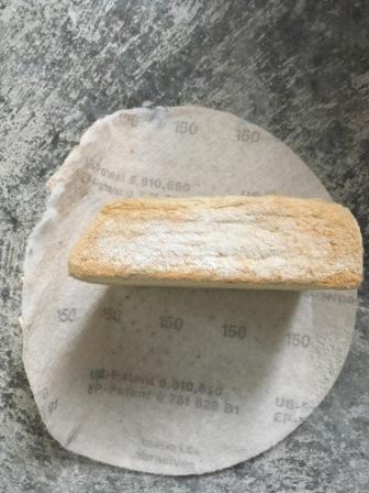
I used a 150 grit sand paper on the Flex machine and left it at speed 4. I was expecting that the sand paper would get blocked up but this did not happen. I was advised and found it very important to sand the edges of the joints and ensure that one does not stay too long on the edges as the paper on the plaster board could be damaged. A light sand in the centre of the joint is how I finished each joint.

I also found it necessary to manually inspect the wall after the electric sander as one is too far away from the wall with the sander to spot imperfections. I made up a hand sanding block for this with a wood fibre board angled to get into corners.

The angled wood fibre board worked out better for me than dedicated sanding blocks and I used a pre-used sanding disc from the electric sander.
Plasterboard Corners
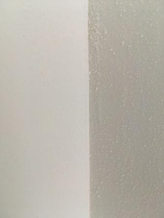
I experimented with the wall corner finishes on whether a sharp edge or rounded corners worked out better. The sharp edges looked like that shown in the top image below and the rounded corner is the image below that. If I was doing it all again I would use the rounded corners as I feel it looks better.

Fire Compartmentalisation
Typically with internal wooden stud walls there may be gaps between rooms at floor level or vertically. For this reason one may want to ensure that fire compartmentalisation is addressed (a previous blog covered this in detail). In order to do this I have chosen a B1 rated fire foam for the floor gaps. It also has a secondary benefit of reducing sound travel between rooms at these gaps. The foam I used was Olive PU-476. The price varies and the best value I found in Ireland was at National Seal Systems in Dublin. I also bought intumescent water based fire sealer for small gaps around the edges of the distribution board and vertical uprights where one partition meets another.