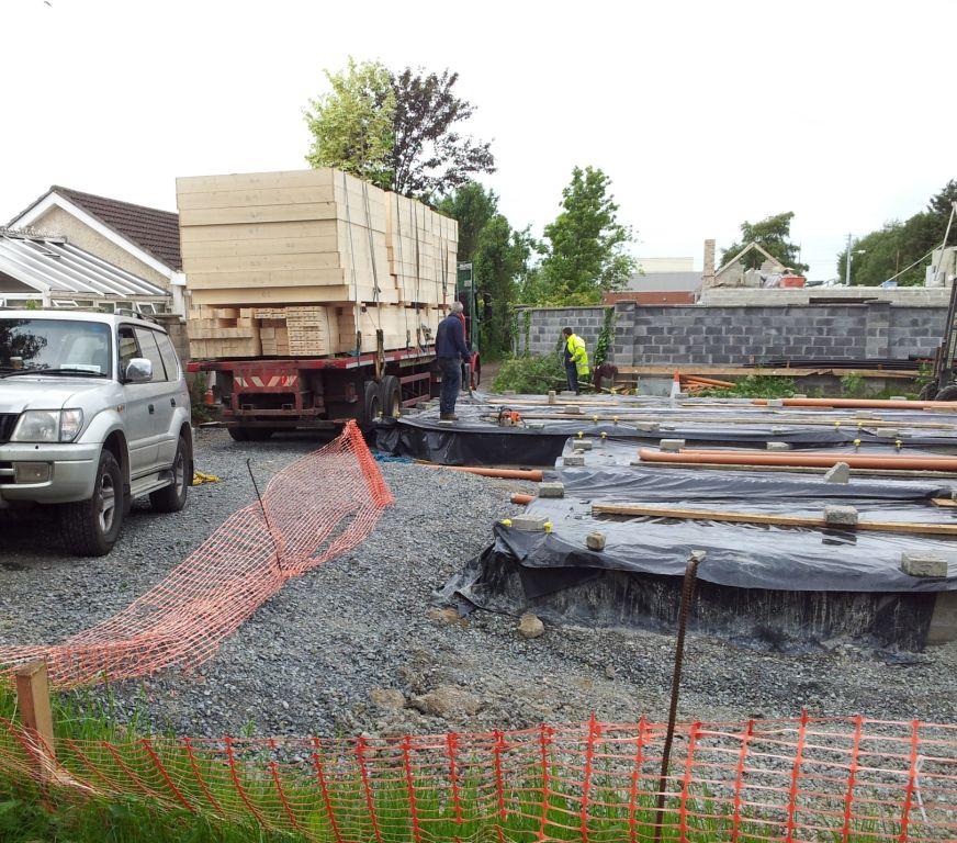
The arrival of the house frame is always a defining moment as it means that stage one of the concrete foundation is ready as per specification.
Self Build Passive House
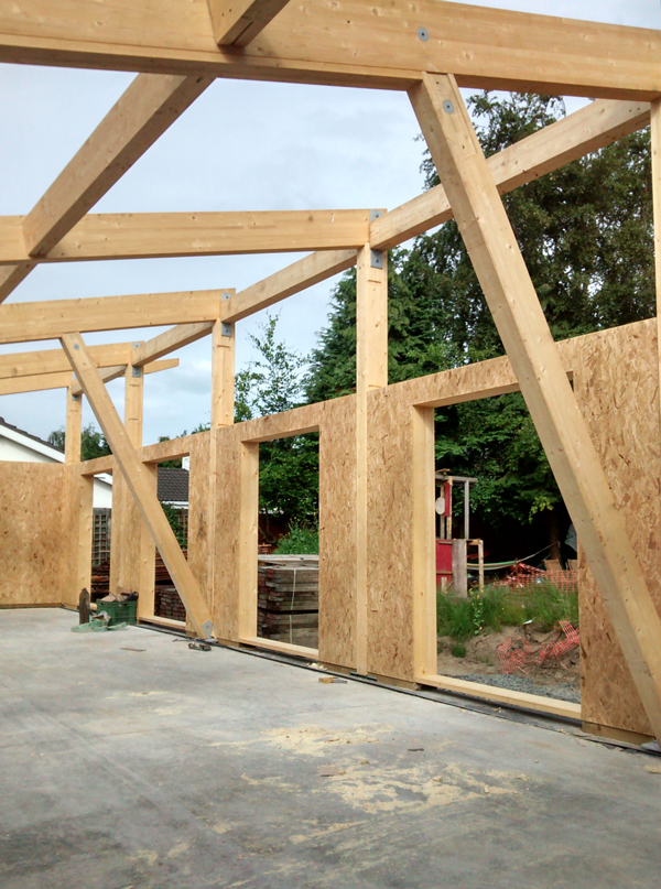
As previously mentioned a few of the reasons for selecting a glulam beam system was that it allows for a flexible open plan design in the future where internal walls can be moved. It should also simplify the air-tightness strategy and the running of services.
Frame Arrival
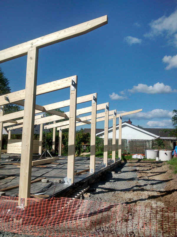
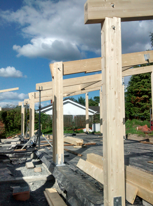
The first few days were spent installing the posts and brackets.
Glue-lam posts Self BuildGlu-lam wall section Passive House Self Build
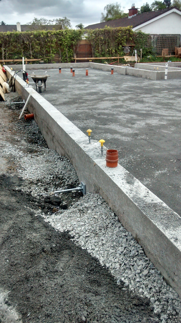
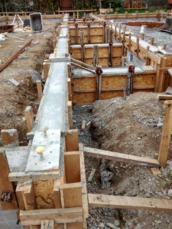
A few notes that may be helpful to the self builder when planning the services such as sink waste, cold/hot water feeds, toilet services. The layout of the foundation services necessitates the early planning of bathroom layouts and even the choice of toilets and shower outlets before the floor slab is poured.
Foundation Services-White pipes are electrical services.
We visited a local bathroom showroom and we were informed that there are a few different types of toilet systems and they require a different pipe outlet location in the floor to ensure that they will fit. One has also to be sure that the layout of the bathrooms and toilets are what you want before the slab is poured.
For the shower outlets one has to decide between the use of trays or a walk in that is tiled flush with the floor or other finish. This will necessitate different floor slab preparations.
Another factor to keep in mind is that showers or sinks that are lightly used may dry out in the pipe trap resulting in unwelcome smells. I am trying to locate a unit with a larger water trap.
For sink outlets waste pipes it is beneficial to have these mounted in the walls so that different arrangements can be facilitated later on. This necessitates the slab pipework being brought up in the centre of the partition or in the service cavity. I have tried to keep all these inside the airtight membrane.
Kitchen Services
These need a special mention as one has to consider a duct for power cables if a kitchen island is used, water drain outlets for dishwasher etc and a cold water feed for a sink. It is practical to have the water main feed coming into the kitchen first before branching to other locations around the house. (This is more than likely the place one expects to switch the supply on/off) . Consider the grease trap outlet location also as they are substantial in size.
Electrical Services
In relation to electrical cables entering and leaving the house one needs to plan for cable ducts to garden lighting, main electrical supply (using special red ducting), rainwater harvesting cables, power for central vacuum unit if mounted outside the house, telephone line, broadband cables, power for outside shed if applicable, control wiring for services in plant room if situated outside, CCTV/alarm cables if applicable or a plan for these. I feel it is better to put the ducts in now as any unplanned cable changes in the future will affect the fabric of the building. My preference was to use a single 40mm duct for each cable with large sweeping bends for the electrical services. I feel it will be easier to ensure an airtight/rodent/insect seal with heat-shrink tubing on each duct.
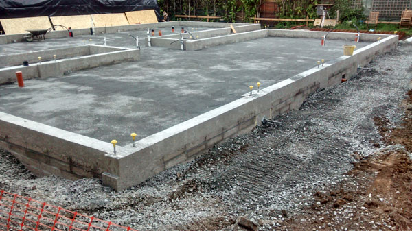
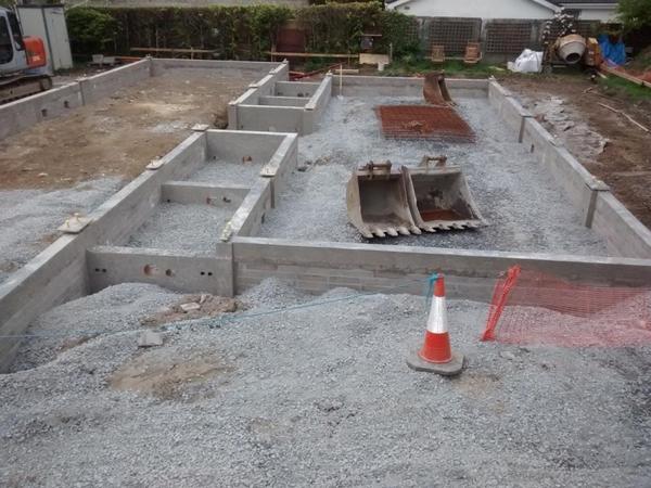
Foundation Services Layout
Separate 40mm ducts for each electrical service.
HRV Drip
The HRV unit may also need a water condensation drip outlet. For this I plan to use a half inch heavy duty pipe that will go outside rather than plumbing it into the sewerage outlet.
Garden Water Supply
Because we plan to use a gravity based system the garden taps will be fed from inside the house using a 1/2 inch or 1/4 inch pipe installed in the foundation. One will feed either side of the garden.
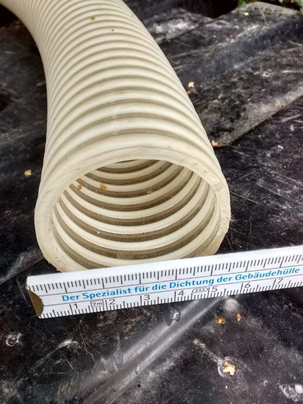
Central Vacuum System
If this is being installed a special flexible PVC duct is required if the unit is situated outside the house.
There are a few tools that I found very useful as a self builder (which are free).
One such tool is Evernote. As self building involves plenty of research and the need to access information. This tool has proved invaluable for me to store information, share information, find information and make it accessible on a smart phone, any computer and automatically back up the information (nothing worse than loosing or not being able to find information). It also allows one to take pictures and have these stored in the same place.
All one needs to do is tag the information (a tag example could be the word insulation)-when you store the price/information you found on the internet about insulation it is stored with this tag and any other insulation data found over time. All pdf documents (these are usually research papers) can be stored also. There is an option to buy the premium version at €40 a year then the individual pdf content of the documents can be searched.
Another tool is Autodesk Design Review 2013. This tool allows you to open autocad files that your architect or engineer may have used for your build. It also allows you to edit these with your comments , take measurements of the drawing and draw simple shapes to highlight issues.
Another tool worth mentioning is Autodesk DWG Trueview. This is more similar to Autocad as it is mainly a viewer (allows one to open files).
THERM
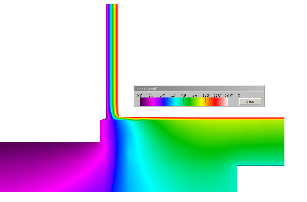
A tool that allows one to calculate the heat loss of thermal bridges is Therm. It was developed by Lawrence Berkeley National Laboratory (LBNL) and again it is free. This tool will show you how cold (and the heat loss) your floor/window reveal etc is going to be near outside walls and the actual performance value so that the real heat loss can be calculated. (One can easily get a feel of the importance of this detail and the energy lost if you see mold/condensation around windows/doors etc ). This software will show graphically how much heat is lost (once calculated) and the temperature/heat loss you can expect on details such as window frames, door thresholds, the steel ties in your block work, the steel beam sitting on your inner wall or foundation etc.
There are two parts to calculating the actual heat loss – the first is drawing the detail (fairly simple and involves time) and the other is the actual calculation (tricky I feel for a self builder). If one draws the detail this can save costs if a third party does the calculation for you).
Thermal image of temperature changes in a foundation with low heat loss. The right hand side is the internal floor. The blue, purple and green colours are low temperatures. The green colour is 5 degrees Celsius.The above foundation with no insulation. The inside floor has a high heat loss when the inside room temperature is 20 degrees Celsius. The small red line on the floor shows a wooden floor installed thus delaying the heat loss.
SketchUP
This tool allows one to model in 3D your house design and carry out a walk through to get a feeling of the internal or external design. It also is used by the passive house institute on their energy balancing software PHPP so it is a worthwhile tool to learn.
Hardware
Other than a smart phone which is a real help when one wants to send/receive files, images or emails and keep things moving on site a device called the Samsung Note 10.1 (2014 Edition) makes documenting ideas and drawings a great resource while on the move. It is only one of a few devices that has a real pen and sketch pad that allows one I feel to replace a piece of paper because one can rest your palm on the screen like a piece of paper and write or draw.
Sun and Climate
Sun Surveyor Lite predicts and visualizes Sun, Sunrise and Sunset positions and times with a 3D Compass on your smart phone. It is useful in identifying the site layout and potential shading issues from trees etc. One can simulate the sun at different times of the year. If one want to do the exercise on paper then this web may be of help- http://www.gaisma.com/en/
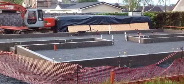
For the Insulation in the foundation we decided to use Kingspan TF70 to a thickness of 200 mm (2 x 100mm). What really surprised me is how much of it was used when I saw it stored on site. (See image below of insulation covered in plastic behind the digger. There was so much of it that when I was ordering it they asked me what housing estate was it going to be used in.)
Insulation on site
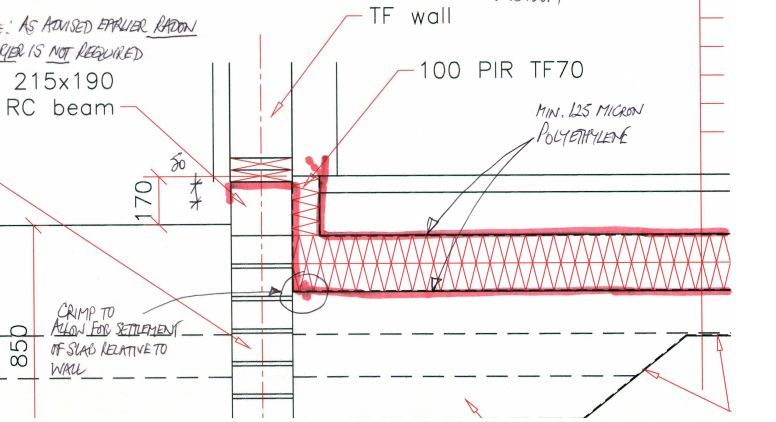
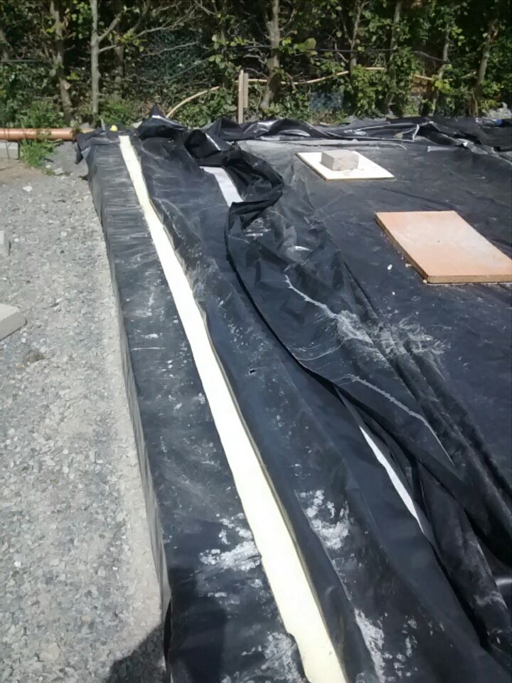
What is perplexing is that the product documentation says do not use it if it gets wet but one still has to try and install it in Ireland without getting wet during the foundation installation stage. The image below shows the 200 mm insulation installation detail.
200 mm insulation and 100 mm perimeter insulation using TF70 .
Services
For the services such as cables, exterior garden lighting, control wiring, main power cables I decided to use single 40 mm ducts with large sweeping bends for each individual cable. In this way I feel the air-tightness installation will be simpler to install as each pipe will have its own airtight heat shrink. (I anticipate it would prove difficult to create an airtight seal around more than 1 cable.).
Steel Fibres (Novocon)
The slab was poured in one continuous go. It appears for this to work properly we need to add a fiber mesh to the slab. They are around 50 mm long with hooks. (See below)
Fibre MeshPoured Slab
Once the concrete floor slab was poured it was then power floated. In order to cure the floor slowly it was then covered in polyethylene for 14 days.
Slab Curing
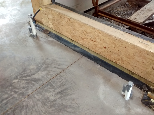
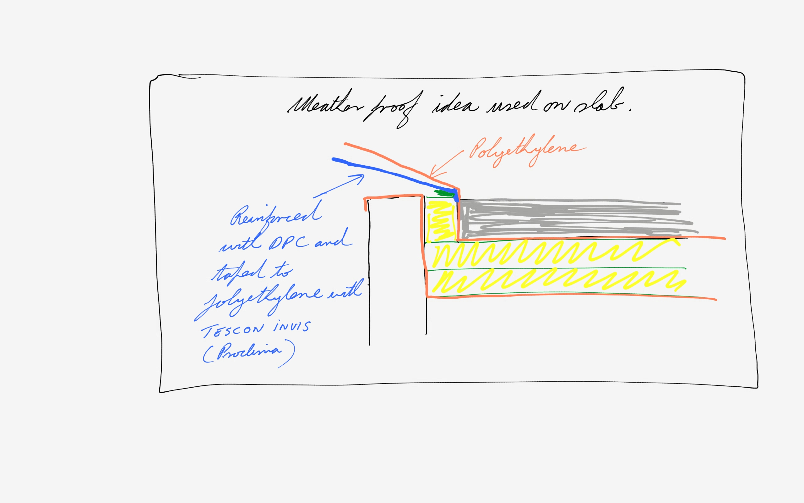
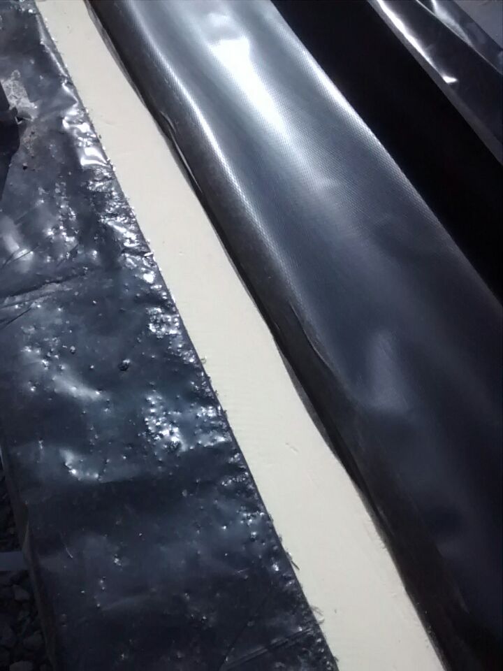
In order to protect the insulation I felt it was necessary to reinforce the polyethylene sheet under the slab before the wooden frame started. In this way I felt that when the rain arrives that it would divert the majority of the water on the slab over the insulation rather than find its way down around the insulation through small holes from construction work (see sketch of idea below).
Weather proof idea.
These are images of before and after using the DPC.
For the building structure we decided on a wooden frame with glulam beams. I considered :
block work with cavity and on the flat with external insulation (I was advised that this was going to be difficult with the number and size of window openings on the south facing walls).
standard wooden frame with panels
Thermal Block -http://www.thermibloc.fr
Poroton Blocks.
ICF (Insulated Concrete Formwork)
Another block that was certified by the passive house institute (but the certificate appears to not have been renewed on the passive house institute web site)
The reason for selecting wood was that I feel that this is going to suit our lifestyle and offer flexibility with the internal layout if changes are required in the way the building is used in the future (room layout or open plan).
The advantages I feel for us will be that when heat is needed it would easily be supplied and if heat was not needed it could be switched off if we are not in the house. The temperate climate in the UK and Ireland is unique (one day 5 degrees next day 13 degrees) and I feel that this will allow us to lower or raise the temperature quickly thus possibly reducing our heating bill.
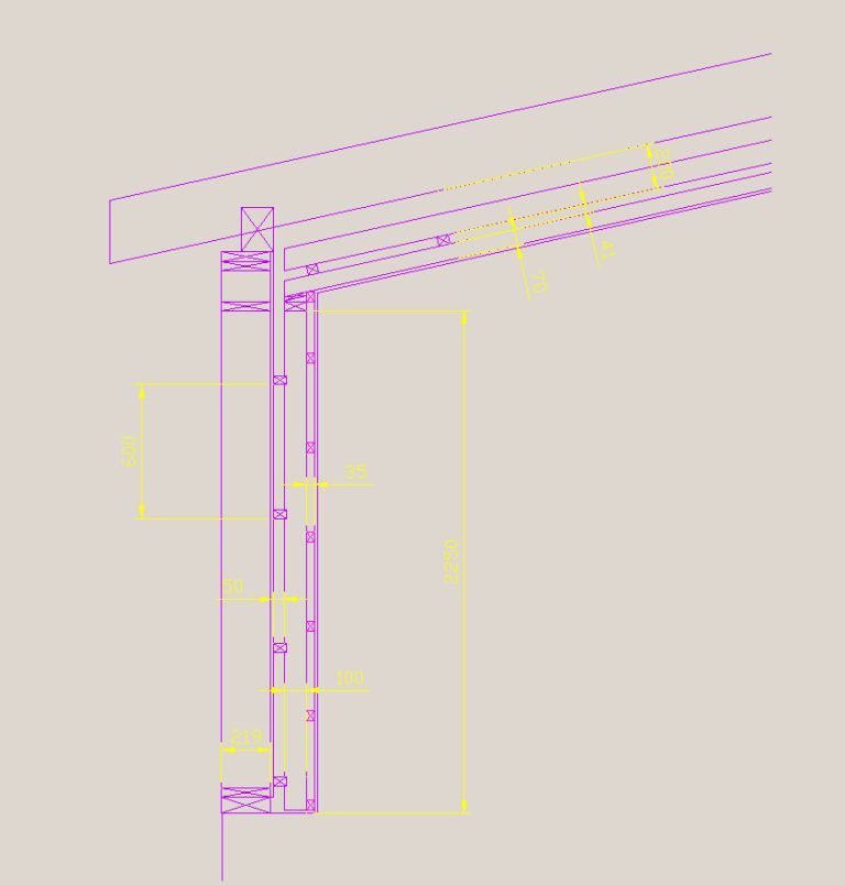
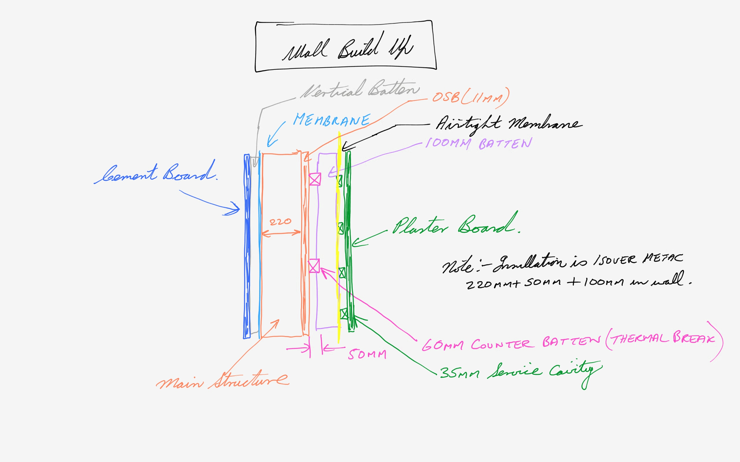
The external wall system will be cement board with an acrylic finish, a ventilated space, and a vapour membrane (Solitex WA) stapled with stainless steel staples with the membrane sealed on the perimeter (to keep wind and small insects out) using a proclima adhesive called Orcon F. The OSB board will not be installed directly behind the vapour membrane but situated 220 mm deep into the wall structure.
(My understanding for doing this is that there is a higher risk of extra moisture being trapped in the OSB board if it was on the outside . By increasing the insulation less heat would escape to dry the board over varying Irish weather cycles. This could then decrease the structural strenght of the board if moisture was not released quickly enough.)
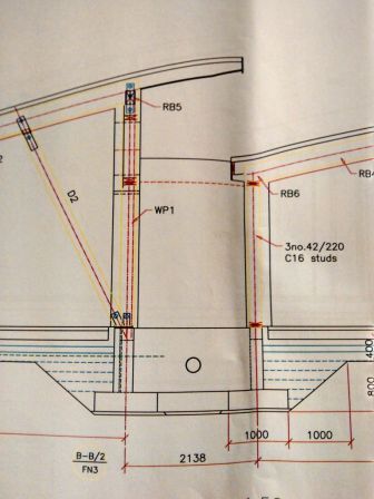
A few drawings will hopefully explain the above.
Wall Structure
Wall Sketch
The walls will be filled with Isover Metac situated behind the air tight membrane. (I am thinking of it as a zoo strategy i.e keeping the fibres behind the glass in this case the air tight membrane). I am considering Cellulose or Hemp on the internal partitions ( I am looking for something that is cost efficient and provides thermal capacity.)
Before the foundation began we had the geopathic stress lines on the plot checked out and any other energies that were on the land in its use over the centuries.
With this information the geopathic stress lines were identified in one future bedroom. The bed was moved to combat this and the other energies cleared.
My understanding is that the geopathic stress lines are like naturally occurring magnetic fields that run under the ground and for this reason we felt it was easy to minimise the risk by knowing about them if they existed on the plot and dealing with them at this stage of the self build.
For example some say there is no evidence that pylons and mobile phone masts can damage your health but we decided not to take a risk by building on another one of these issues known as geopathic stress lines. We are also addressing potential risks from other energies such as mains electricity, wi-fi etc. For example one person may be susceptible to hay-fever, a particular food allergy, mobile phones etc and another not.
Like all these things there is no way to be sure how one might be affected. I think some people are more susceptible and we will try and design these potential risks out of the self build for this generation and the next generation who chose to live in the house.
Of all the things in a self build the one item I have learned to respect is the foundation.
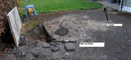
The details I feel a self builder should watch for are the above ground survey , soil inspections and underground survey for services. We were lucky with the underground sewer survey as we relied on council drawings during the design of the house but as we found out these did not match the actual design.To our advantage they were further away than expected. (They could have easily been closer than expected causing significant delays and cost to the project and potentially could have meant that the design of the house would need to change). So my advice for those who are building in a built up area is do the physical survey especially with sewer lines-we used a CCTV survey and asked for a hard copy to help with the county council negotiations.
It may also be advantageous to have the sewer line physically mapped out above the ground using an electronic locator/tracer at the same time. This will help identify the actual route and height the house needs to be for connection to the main sewer.
Also it is worth noting for the self builder with a house already on a plot that the bottom corner of a garden on a site could also be used to bury building rubble. When we started the foundation for the shed this is what we found and this increased the cost.
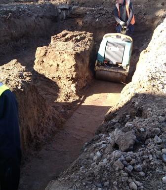
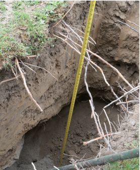
Soil Test and Sewer Line One of the soil test pilot holes indicated a cost increase because of silt and sand before we started. (As you can see below the soil is giving way as we came across a layer of sand)
Soil Foundation sample holeLocation of Sewer LineSewer Line Depth 47cm
Deciding on the foundation type. The foundation design went through many iterations. The cost of the foundation was high because of a number of factors–the soil type, the house design and the house size. The following designs were considered and costed.
Insulated Raft with Foamglass
Insulated raft with XPS (polystyrene)
Piles
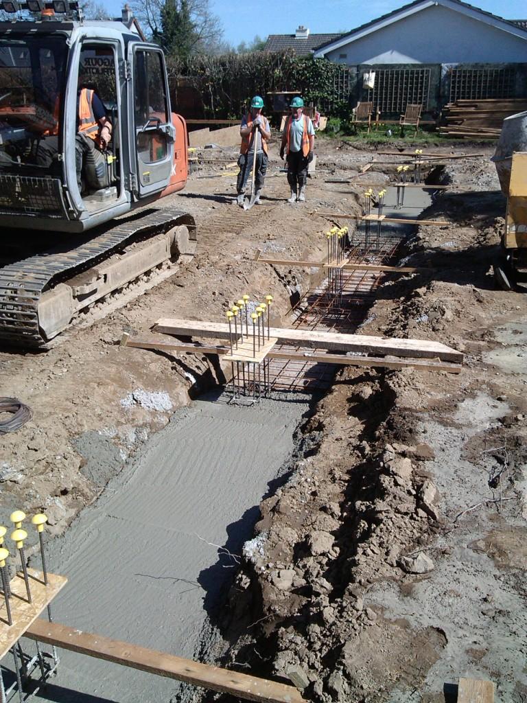
Strip Foundation with steel post reinforcement
Strip foundation with ring beam.
The builder and engineer were consulted to establish which design would have the best chance of coming in on budget, keep the construction detail as simple as possible and result in no long term unknowns. The strip foundation with ring beam was selected.
The plan is to install led lighting. I will also install low level background lighting that operates on a 12 volt DC supply. The idea is to have this low level lighting operating from dusk to dawn and act as a backup to power failures and hopefully reduce power usage by not having to switch on/off the main lights as one goes around the house at night. The light level planned will be equivalent to the light output of a candle and these will be placed approximately 2 metres apart in hallways and bathrooms near the floor level.
For the principle lighting I will be using Sharp Zenigata Leds that have a very high Colour Rendering Index value (CRI). The CRI is an important factor in trying to reproduce the colours of everyday items. One may have noticed that the majority of led lights reproduce colours poorly ie. red does not look like red, green does not look like green etc.
The CRI value is one of the standards used to compare the colours reproduced by Led lights to that of a halogen/incandescent bulb. Most manufactures may only indicate a colour temperature figure like 2800 degrees kelvin. This works independently of the CRI value. No LED manufacturer has of yet been able to reproduce the colours an incandescent bulb or halogen bulb can reproduce.
Below is the best explanation of CRI values I came across.
Sharp CRI Explanation Graph (The orange line above is a typical led and the green line is the sharp led and how it reproduces different colours)
Reliability
A factor that determines the reliability (life) of LED lights is the management of heat and the ability of the manufacturer to try and squeeze lots of electronics into a lamp that operates at around 60-100 degrees Celsius (high power type that can replace 50 watt halogen lamps). Thetwo factors do not work together so I plan to separate the electronics from the heat by only installing the LED lamp in the ceiling fitting and use a separate device called an led current driver to power up to 3 led ceiling lights. In this way I hope to get the full 10-15 year life of the led lamp. (I will probably want to change them before that time though as the technology advances).
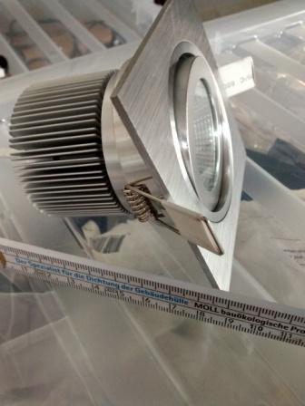
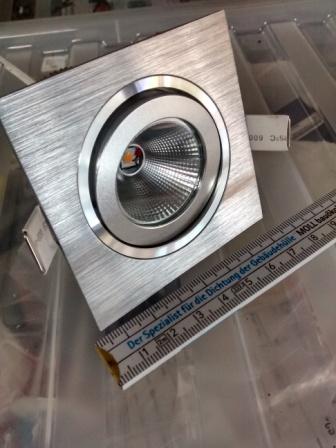
Self Build Housing for the Led lights.
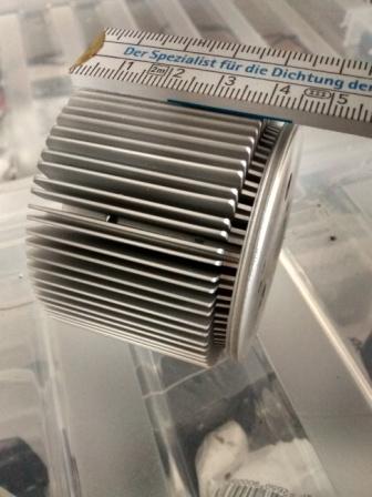
I could not find a Led lamp that used the sharp petite zenigata high CRI led and be sure it was designed properly. For this reason I decided to build my own. In order to do this one needs a suitable heatsink (a device to remove heat efficiently) and enclosure for mounting the led light in the ceiling. A heatsink will usually have a power rating that specifies what size led it is suitable for.
Below is a 6 watt heat sink. This is approximately the size heatsink that is required to replace a 50 watt halogen down light. One can see the challenge manufactures face in trying to adapt led lights to fit into existing halogen lamp housings with all the electronics and a suitable heatsink that would extend the life of an led.
Heat Sink typical for a 5 watt Led
The principle as stated before for this self build design is that it allows me to remove all the electronics to control an led into a separate enclosure that would not be effected by the heat. By doing this reliability is increased. In other words simplify the design by lowering the component count and thus extend the life. The pictures below are the finished Led Housing .
Finished Led light fittingFront view of Led light fitting
I now need to look into rainwater harvesting as the location of a tank needs to be planned so that the inspection covers can be kept as discreet as possible in the garden design. I will put the inspection covers in the footpath area. I am only installing the rainwater harvesting initially to feed the toilets in the house, water plants and wash the car with a gravity fed tank located in the house (this looks like the simplest method to maintain and install). My reason for only dealing with the toilets is the idea of using fresh water to flush toilets is a difficult thing to accept from an ecological point of view and toilets are a significant use of water.
Whole house rainwater systems look complicated from a health, engineering and chemical reaction point of view. Issues I understand that need to be dealt with for whole house systems are such things as if the PH level of the water falls below 7 it attacks copper pipes, the stagnation of stored water/pollen attracting pests, chemicals such as lead collected from roofs etc.
The System
There appears to be a need to have a few inspection covers and have access to these. The first inspection cover will consist of a coarse inline filter for collecting leaves and other debris with an overflow outlet, the rainwater harvesting tank inspection cover (for servicing the pump or cleaning out the tank)-some have the inline filter built into the tank. Our new build installation also needs a soak-way and inspection cover as part of the planning application to ensure that the soak-way can be cleaned out.
As the foundation work is being carried out I plan to install a 2000 litre unit in the ground (the water in larger tanks can become stagnant and smell if not used ) and a smaller unit in another location in the garden above ground fed from a different roof. I will use this unit to prime the main tank if necessary as it appears some systems prime the main tank with fresh water if it runs dry –why would one fill a rainwater harvesting tank with fresh water and how does one know it is working correctly?. My strategy is to prime the main 2000 litre tank using a different roof if the need should arise and have a separate fresh water feed only to the cistern gravity tank in the house with a 30 minute bypass timer. (If the rainwater main tank runs dry I will only top up the cistern tank in the attic space with fresh water). If I was to use a manual or automatic bypass I can see the fresh water supply being left on inadvertently. The most cost efficient approach for the tank and filters that I found are as follows :
2000 Litre Concrete tank €450 from Carlow Providers Phone 059 9145103
Another important point for any tank is the need to have a calming input (when water comes into the tank the objective is to ensure it does not mix the sediment settled in the bottom of the tank with the end result of supplying dirty looking water in the house. ) I will look into this later on once I have researched pumps in more detail. In relation to pumps/controls that are available I feel they are too expensive to buy, run and are complicated (from €250 to €600 and use 500 watts to 1000 watts of power-a small electric fire ) . In the next blog I hope to find a solution that will cost no more than €90 and is simple to maintain and reliable.
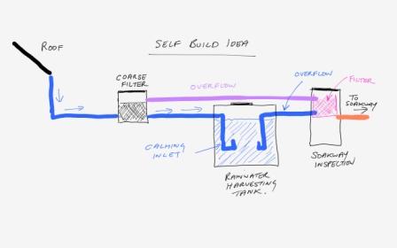
The Current Design
I am evaluating this design I put together and I am thinking of putting a straight outlet into the soakway so that any pollen/debris gets washed directly into the soakway inspection chamber . My reasoning if correct is that this will reduce the smaller debris from stagnating and smelling when the tank overflows.
Self Build Rainwater Harvesting
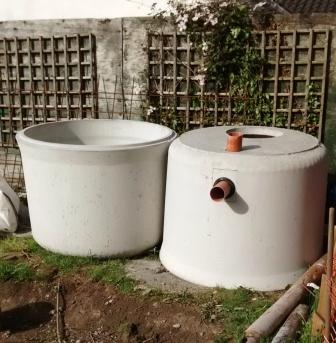
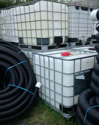
Above ground option for storing water
I came across these storage tanks at around €50 (value for money) . I think they have a capacity of around 1000 litres . Lawler Pipe Sales in Johnstown, Naas at 0862561629 can supply them. One would need to paint them black or ensure that light does not cause algae to grow.