Exterior Cladding Decision
There were a number of choices when it came to the exterior cladding. Because the house is a timber frame I went for a ventilated facade with cement boards. The decision for selecting this was based on the following:
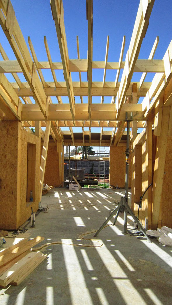
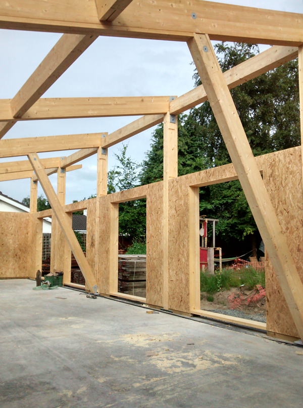
- Because the house is highly insulated very little heat will travel through the wall structure. This entailed changing the wall build-up on the advice of our timber structural engineer. On a normal timber frame one installs a rigid OSB board on the outside and this then would typically be covered with a membrane and then battened for the cement board or tied to block work. When the timber structural engineer carried out a Wufi analysis (hygrothermal analysis-how the wall behaves with our humidity levels in Ireland) he advised that the structural strength of the OSB board would be affected if we placed it outside because of moisture build up. The OSB was then placed inside with only the vapor barrier on the outside and then the outside was battened /counter battened for the cement board.
- My preference was to use block work on the outside (because of cost advantage) but this showed up in Wufi as needing large amount of ventilation and it would not perform as well as a cement board or a wood finish wall. It seems that if one used block work the heat from the sun would take a long time to reach the ventilated space. The ventilated space it appears requires two pieces of physics to work correctly-Thermal Buoyancy (warm air rising and creating a drying out environment) and Wind for the ventilated cavity. Relying on one of these I felt was a risk I did not want to take.
- The other reason for selecting a ventilated cavity versus using an externally insulated (with a non breathable product) was the provision of a second level of protection to the wall structure if there was a fault in the external waterproofing . If for example water leaked in around a window detail it would dry out if the wall was ventilated but if water got in behind a wall that was externally insulated with Polystrene/EPS/PIR/PU the opportunity to dry out was I felt limited.
By selecting a cement board (around 12mm thickness) if the sun shines on this it would within a very short period of time let the heat transfer to the inside of the ventilated cavity and increase the drying out of the wall and also keep the insulation dry so that it can perform at its rated value.
Some Details
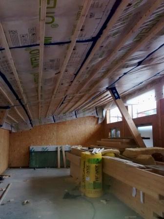
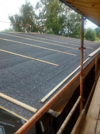
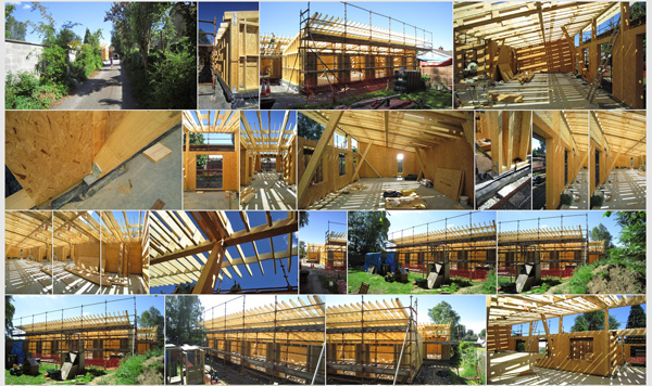
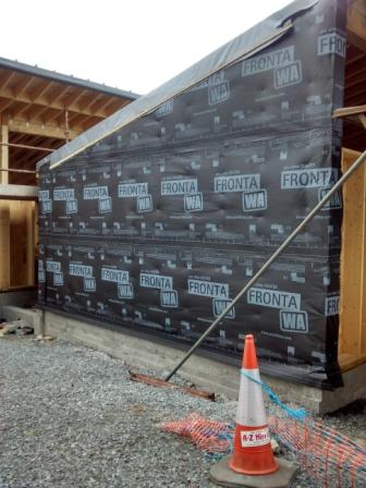
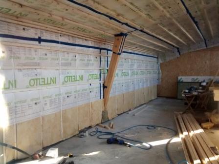
The membrane was glued around the external structure of the timber frame and wall to ensure that no wind would be blowing over the face of the insulation ie. Minimise thermal looping.

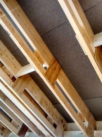
The membrane was placed over the Insulation and glued to structure as seen above.
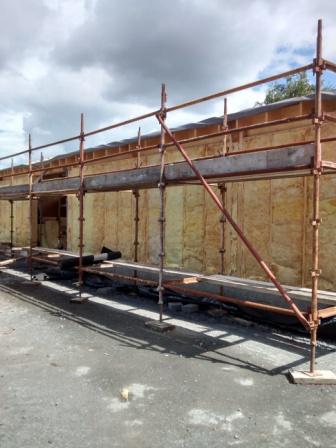
External Membrane applied over Insulation
Battens for Cement Board Cladding
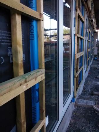
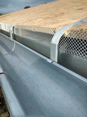
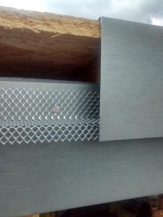
Aluminium ventilation vents for walls.

Cement Board sample
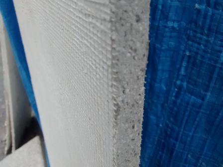
Cement Board Sample
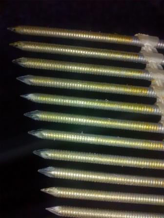
The Cement Board is screwed onto the battens with stainless steel screws. A base coat and mesh is applied first and then a primer. The final finish is a Ral colour acrylic render to make the cladding water proof. If one has a walls facing south west and they are subjected to high rainfall it may be better to install a Silicone Silicate render or check that a chemical agent is included to reduce/eliminate algae growth that can appear as a green discoloration on the render over time.
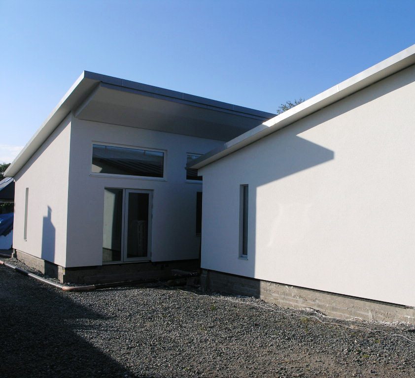
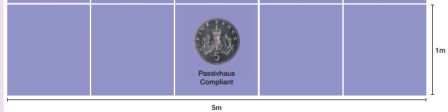
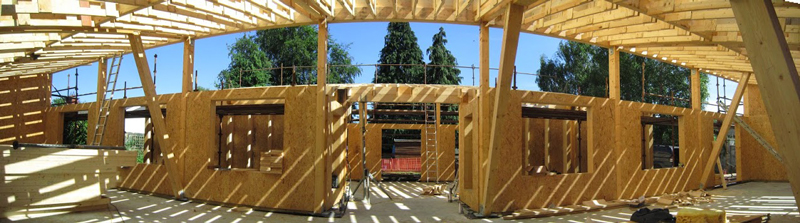
The overhang underside was also clad with an acrylic render. The image below shows the overhangs shading the top windows. For example by around 9:30 AM in June the top windows are completely shaded for the sun and by 14:30 all the lower windows are in shade in order to protect the building from overheating.


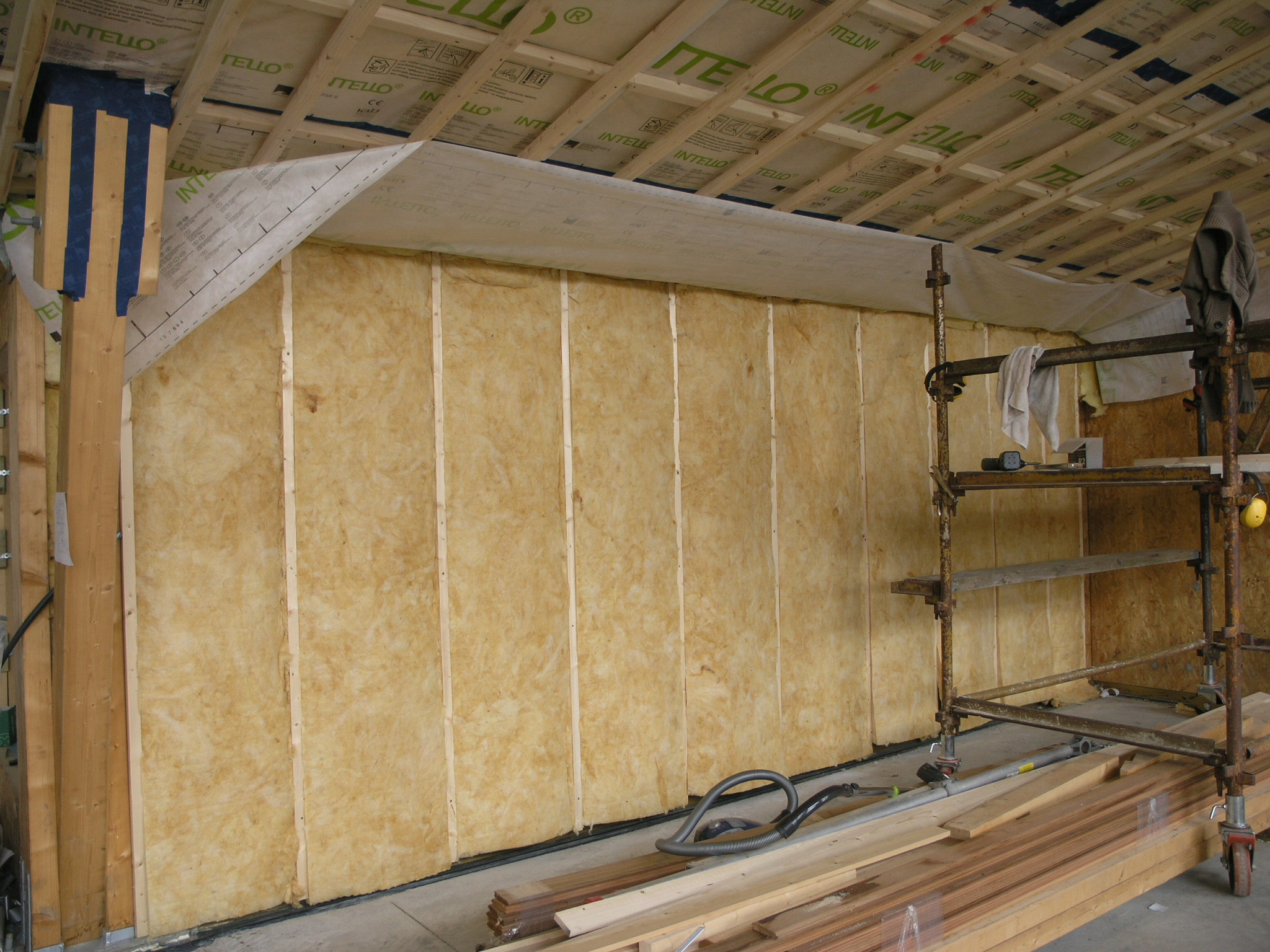
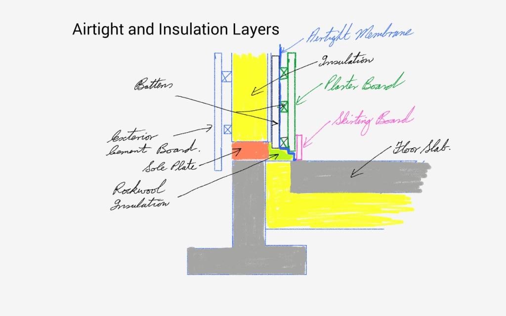 Wall Layers with Insulation